Bubbles ~ The Arduino Dog Robot with an XBee Radio (Part 1)
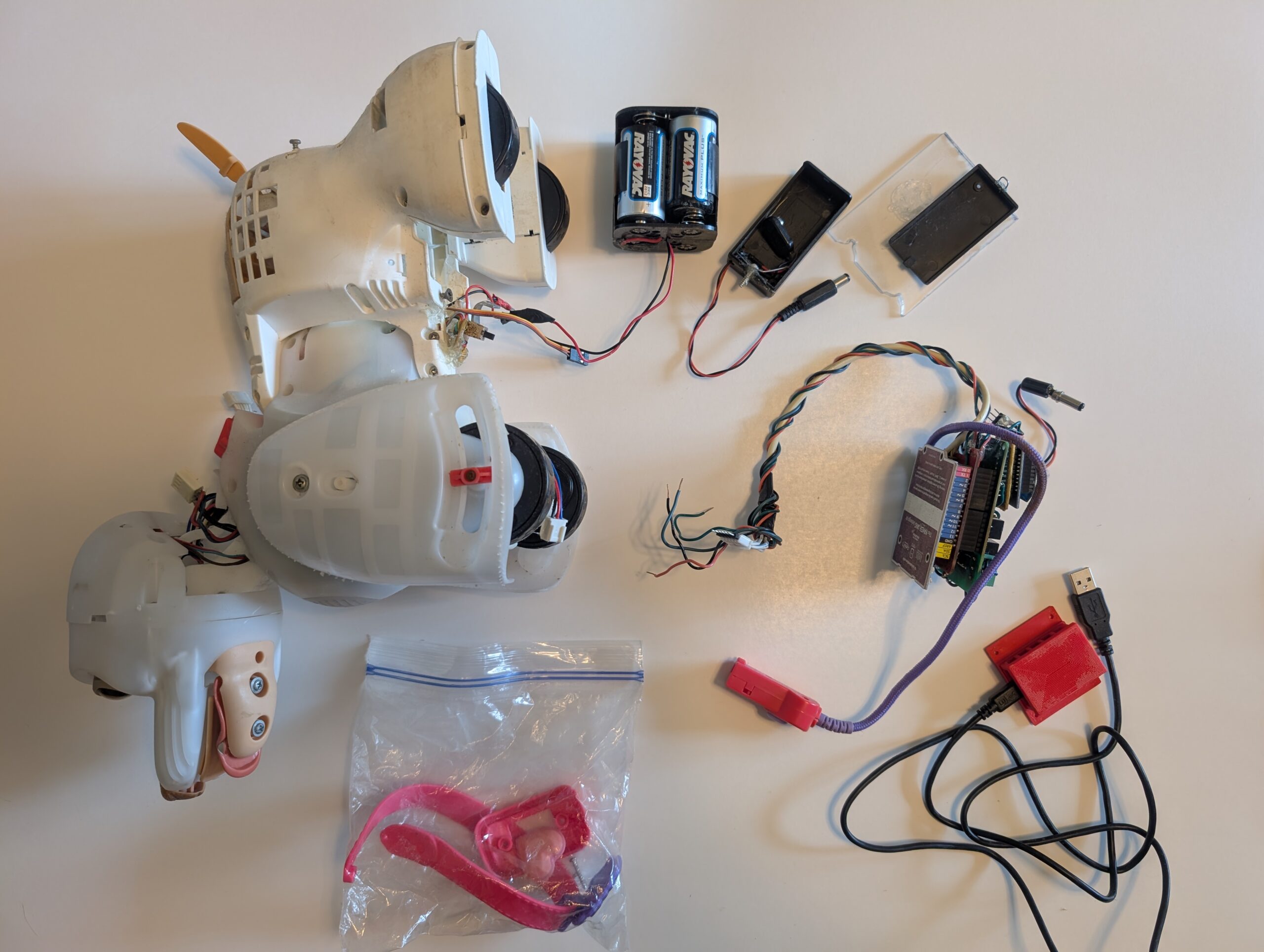
TL;DR: I skinned a dog toy, slapped an Arduino on its posterior, and then commanded it to move over radio.
Overview
The following was an unhinged teaser I wrote in a blog post years ago. I think it speaks to what happened to poor Bubbles. I will (of course) go into greater detail later in the post.
OK so now onto the secret project. Well it is not really a secret and in fact my g+ picture is of him. Its my robotic dog bubbles, so far just a simple deskinning of a toy dog and screwing an Arduino to his posterior have turned him into the most amazing puppy of them all. However he is not complete. Last weekend I did get his neck removed from the gear box and now have it driven by a servo. Also I have given him the ability to backup since the manufacture decided that toy dogs can’t go backwards. This led to an amazing adventure in time travel… er gearbox rebuilding that kept me pleasantly entertained for hours of useless time. Here are some pictures of this fun.
Remember when G+ profiles were a thing? It has been a while since I visited this project.
Origin Story, Timeline, and Musings
Bubbles wasn’t always in such a sorry state. He (originally a she) was a gift my little sister received (for Christmas or birthday, I forget which). The toy line was Hasbro’s FurReal Friends GoGo My Walkin’ Pup. My sister enjoyed this toy for a time. Then as she got older, it was neglected in the closet, gathering dust and battery corrosion. By the time I received it, Bubbles was ready to be sent to the garbage bin.
I couldn’t do much in regard to the fur matted with grime and leaked alkaline deposits, so I carefully removed it (affectionately referred to as skinning). The battery box was ruined as well, so I cut that out.
I then replaced the battery box with two 2x C battery holders from Radio Shack wired in series. I shoved these back into the old battery holder space. I had to move the power switch, which was originally integrated into the battery box, to the outside, underneath Bubbles (hence male).
Some sketchy mechanical implementation of a battery box cover / holder later and he was up and running.
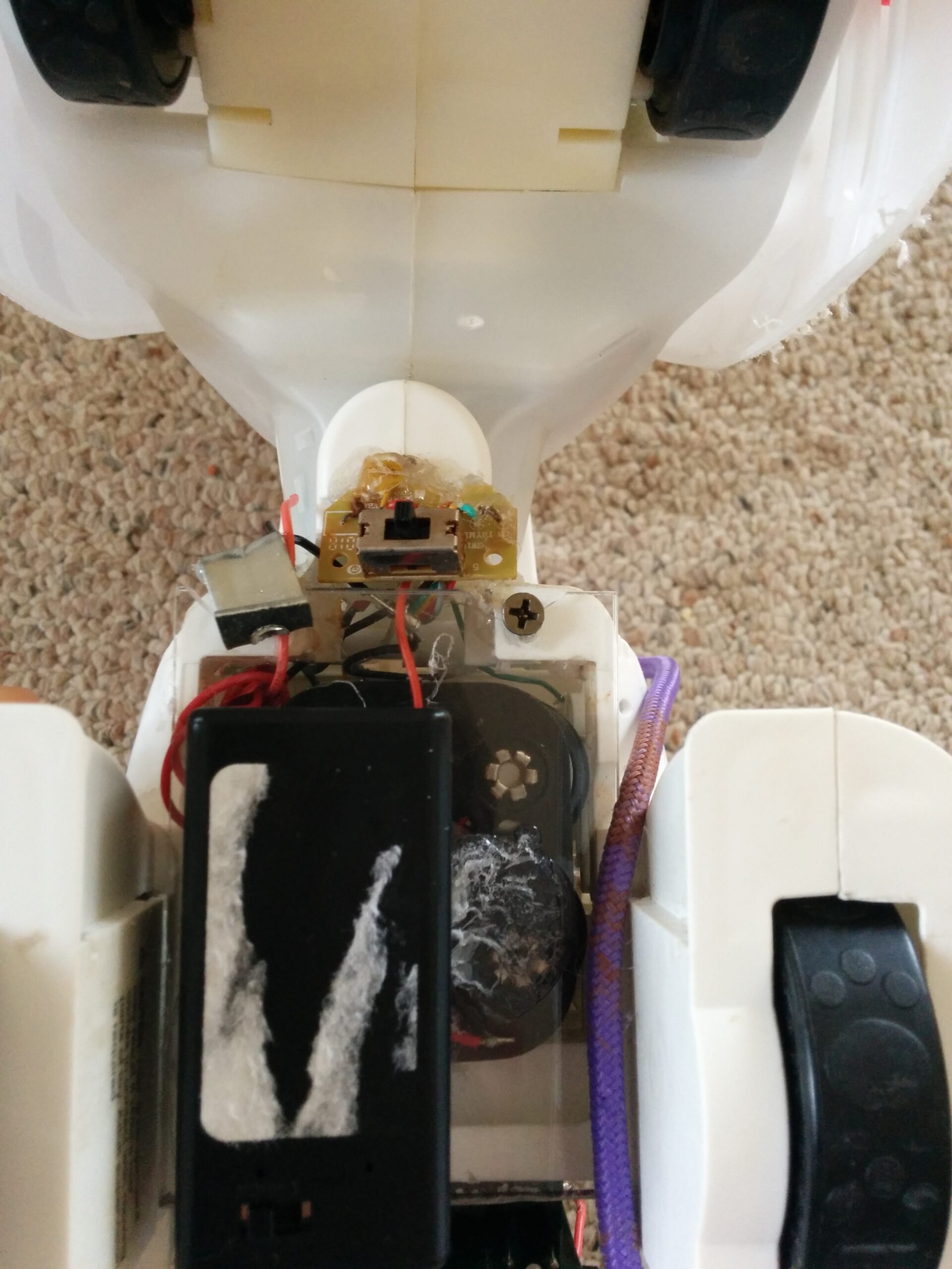
Not the prettiest battery box solution but it held together well enough to work on the more interesting control problems.
Next, I needed to figure out the controls mapping. Bubbles had a wired remote leash with buttons for forward, backward, left, and right. I chopped off the remote and wired the leash lines up to a bank of toggle switches as a first manual prototype. Once I documented the common wire and the control wires, I purchased a relay shield (also from Radio Shack), and wired everything up to an Arduino Uno.
I mounted the Arduino stack to the posterior of Bubbles. The robot body had a cutout perfectly shaped for it already, which was really handy.
It was then time to write the first control code. I used a modified version of RoverBot’s control state machine as the steering operations were similar. RoverBot’s autonomy is a wall-banger (drive until you get close to something, then turn), so Bubbles needed a range sensor too. For a while he had an ultrasonic sensor hot glued to his chest.
After this initial control work, I realized a couple things to be improved. First, I wanted to add an RGB LED to Bubbles’ translucent head in order to signal emotion. Second, I needed independent control of Bubbles’ neck (again to signal emotion). Third, I needed better control over the drivetrain. Lastly, I wanted to remote control Bubbles from my PC.
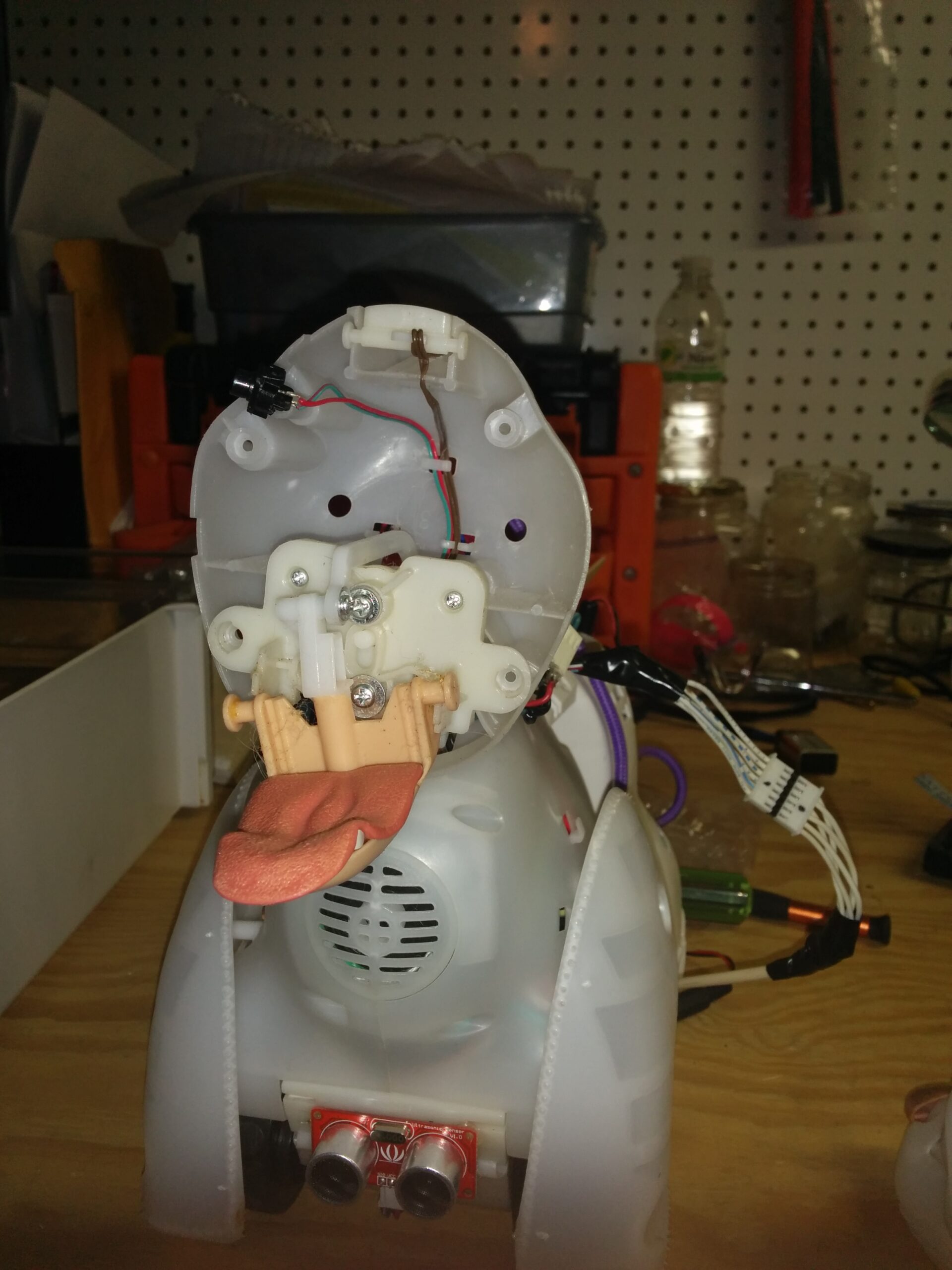
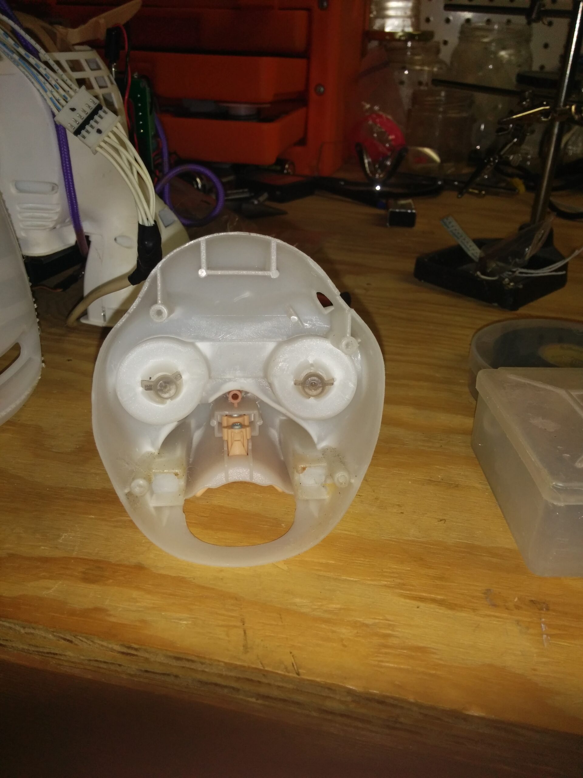
Everything the toy did (head, torso turn for steering, drive, tail wag) came from two motors and a lot of gearing and clutches. That keeps the toy cheap, but it means every function you want to take over is tangled up with another one inside a gearbox.
The head / neck changes were pretty straightforward. I had to do a teardown of Bubbles to place the LEDs and route the power, ground, and signal wires. The neck servo went the same way. The only challenge there was disconnecting the old gearbox. I couldn’t reuse that gearbox as it was multi-function based on a directional clutch.
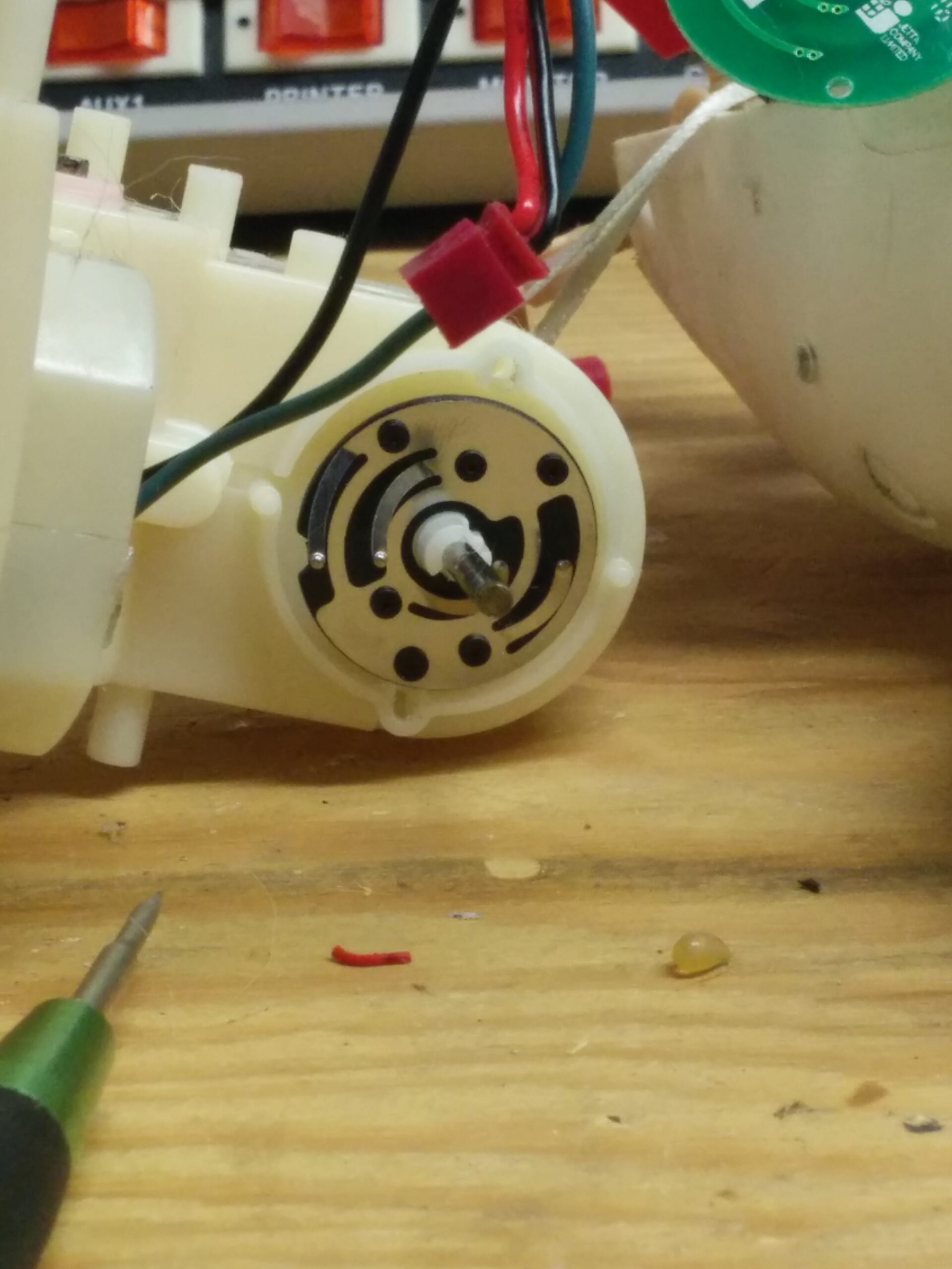
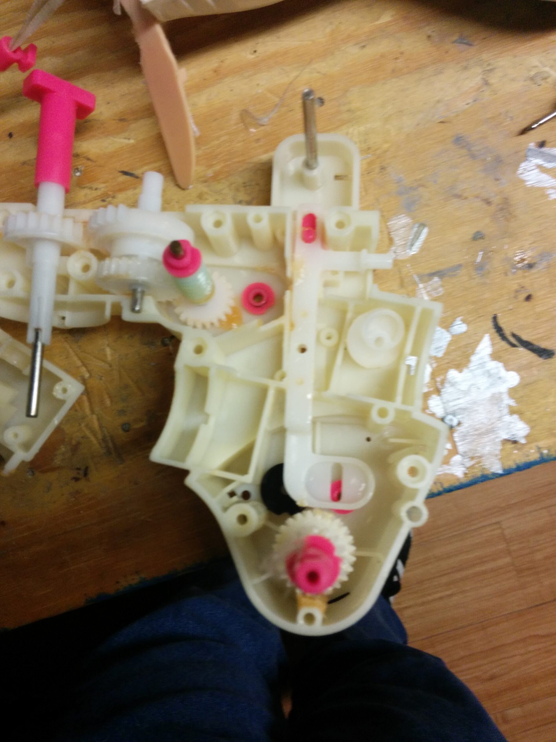
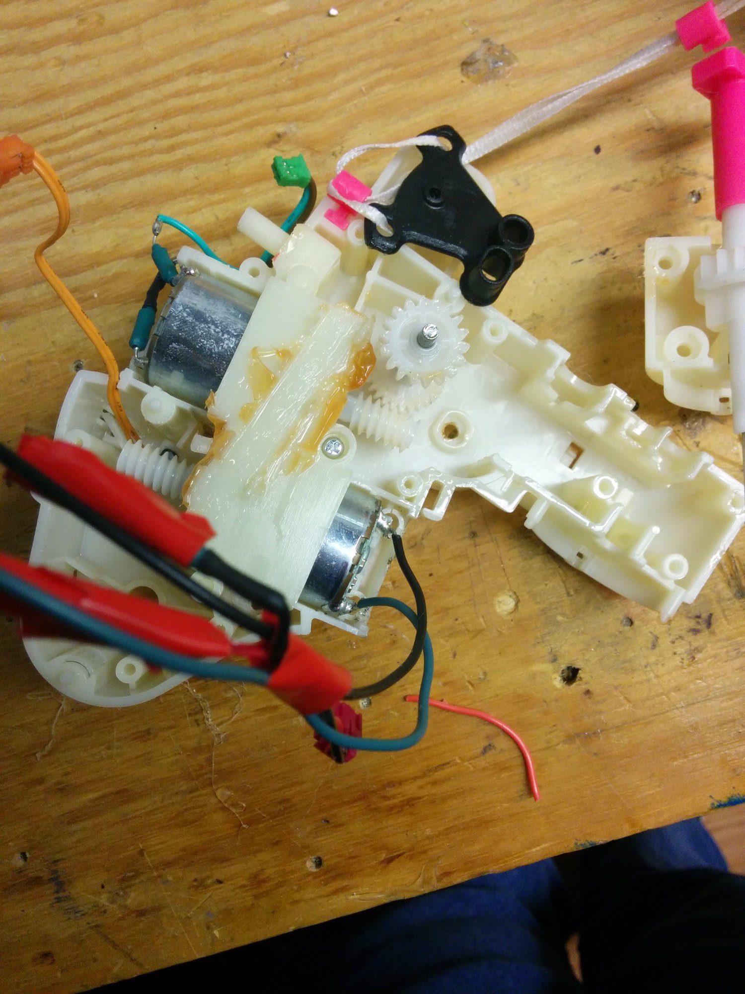
The drivetrain motor / gearbox was also a problem as it was multi-function with forward / backward plus tail wag. Bubbles would randomly stop moving, go forward, or go backward even when commanded to walk by the remote. I wanted to keep the gearbox as original as possible, but at the same time have predictable control for the autonomy state machine. My solution was to tap off the control signals to the motor and the motor itself into a header. Worst case, I could jumper them to get original behavior. Best case, I could access the control state and direct drive the motors.
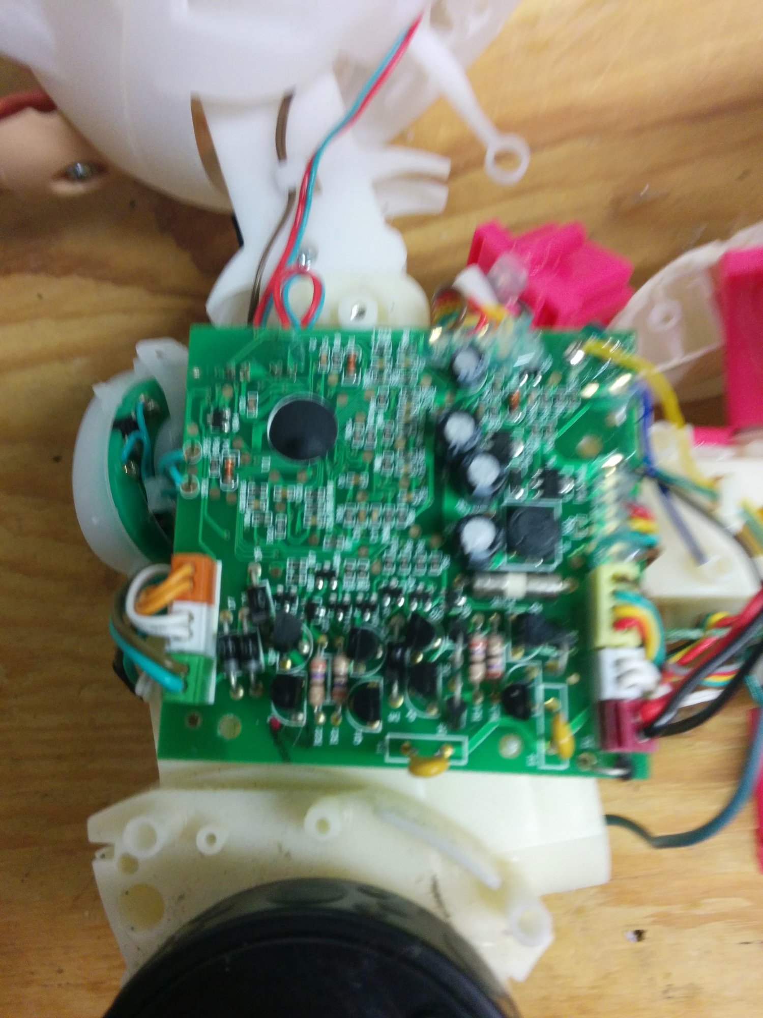
The toy’s original control board, before anything was tapped.
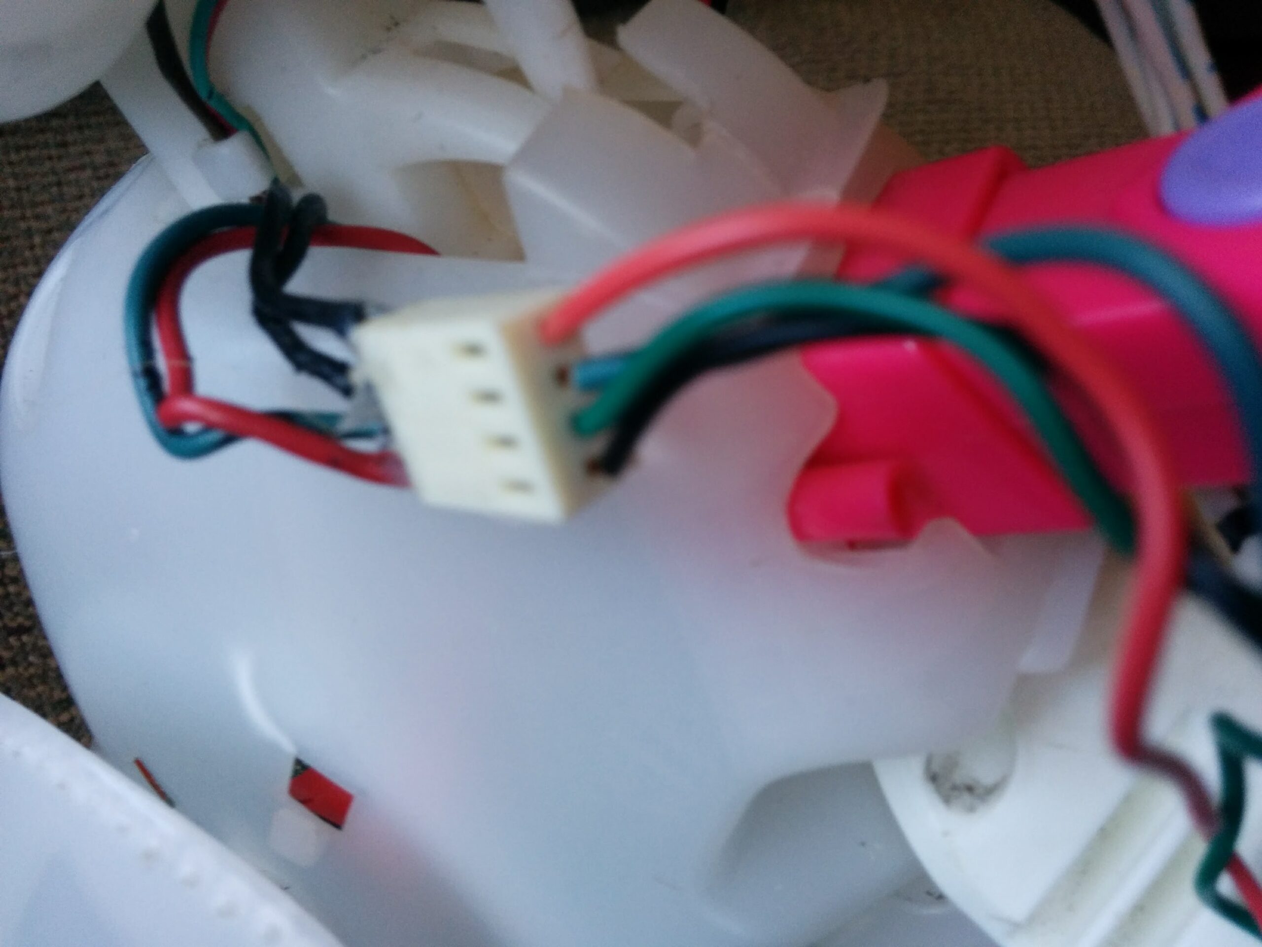
Header with motor breakout and control breakout. Janky but sufficient for testing.
This attempt to control the motors did not work as well as I would have hoped. I don’t remember exactly what went wrong, but I suspect the relay and diode approach I took was the wrong idea to begin with. Tapping the motor wasn’t a bad plan; the execution was a bit beyond my skillset at the time. However, in building this system, I built a lot of the foundational skills needed for later projects, education, and career.
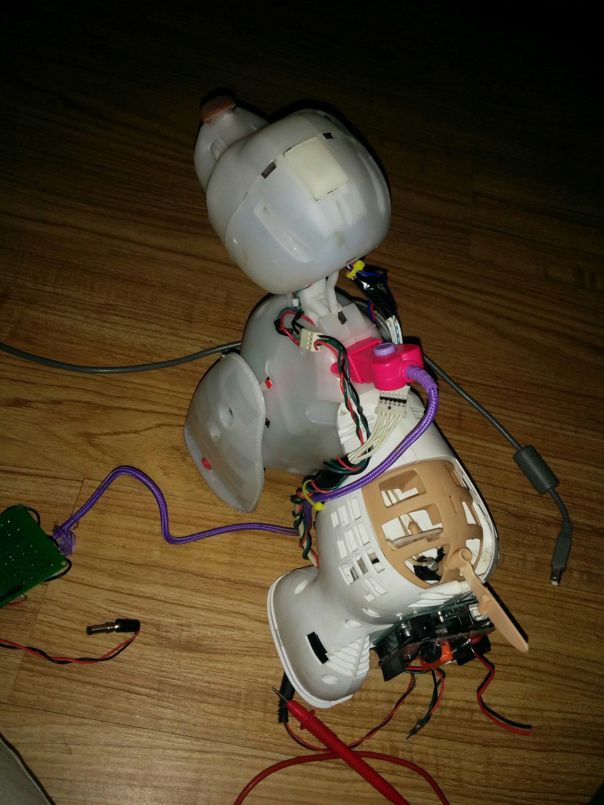
Debugging motor control board built on a protoshield. Needs a Rev2.
Lastly, I wanted to control Bubbles over radio. To do this I purchased two XBee radios configured as a UART pair (transparent serial mode, so the Arduino just sees a UART). One connects over UART to the Arduino. The other, through a breakout board, connects to the PC over USB as a virtual UART. I also 3D printed a little red enclosure for the PC side radio.
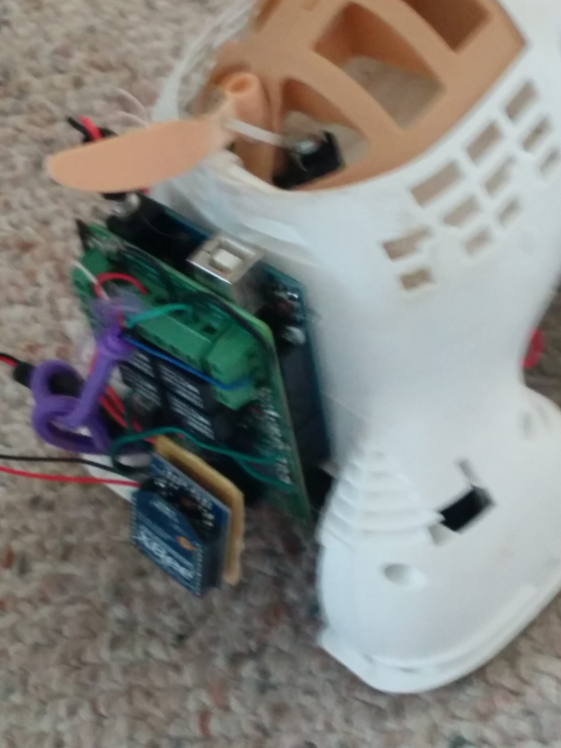
Excuse the poor quality image. Shown is Bubbles’ posterior with the XBee radio dangling off the relay board.
I had a new version of firmware to write. I refactored the autonomy state machine, added basic control of the LEDs, neck servo, and motor controller, in addition to the relay control. Then, I built out a JSON control structure to communicate between the PC and the Arduino over the XBee UART link. Bubbles’ firmware would have both a teleoperated mode and a lower-level autonomous mode.
This development effort went so-so. I did finish that version of the firmware and got a Python app going that served a webpage for control, but the web app never got very far. It is the least developed piece of the project.
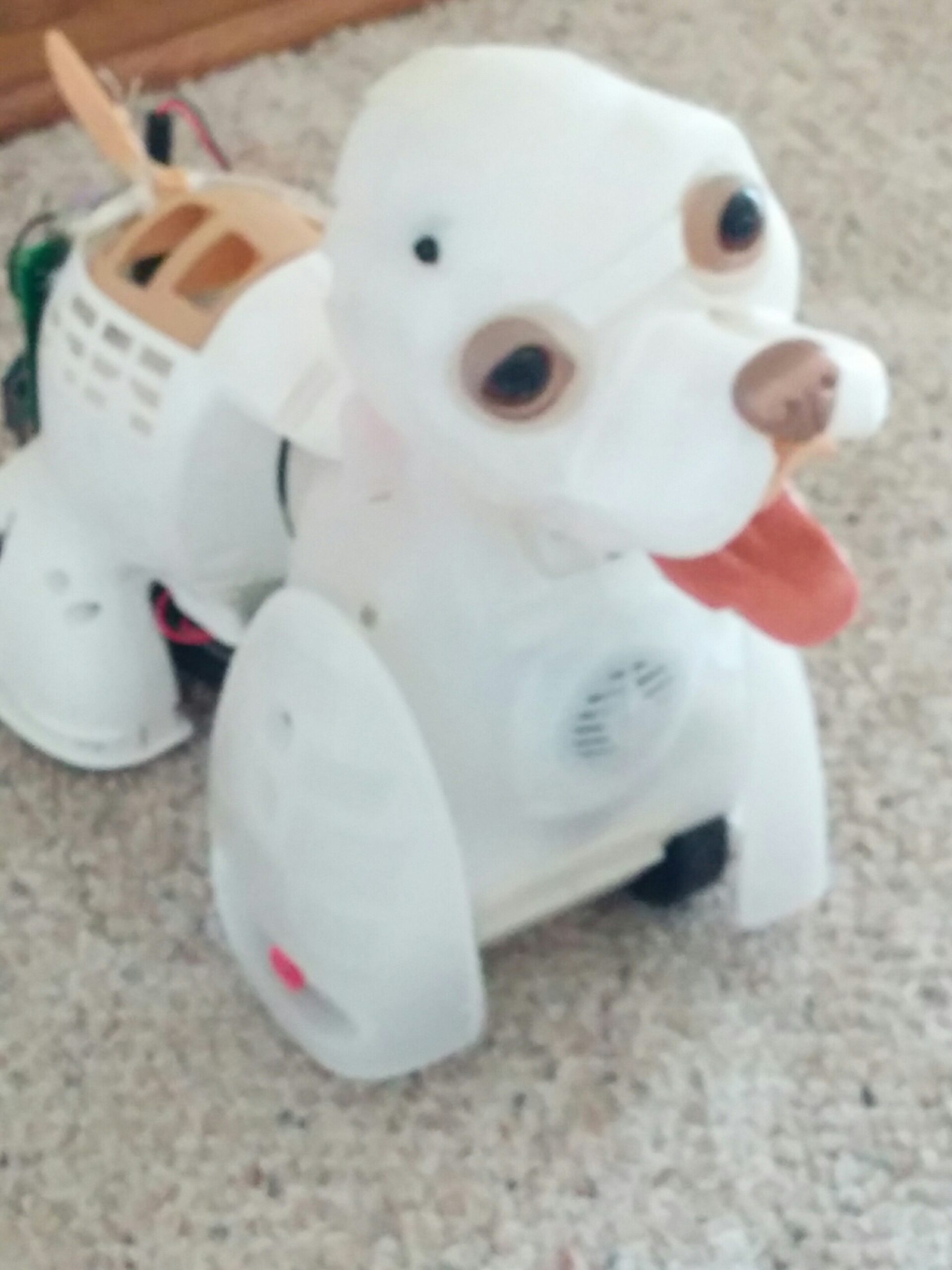
View of Bubbles from the front. Isn’t he adorable?
Hardware Summary
Bubbles is in dire need of repair. But before I do that (as another post) I want to document what we currently have, what needs a rethink, and what needs to be purchased.
The biggest known problem is power. The neck servo runs off the Uno’s 5V regulator, which runs off a 9V battery. When the servo stalls, the rail sags and the Arduino browns out. That is why the power subsystem is item two below.
Outlining the future goals of Bubbles:
- Repair to functional teleoperated control state
- Rethink power subsystem
- Neck servo currently browns out the Arduino
- Rethink sensor input
- Previous was ultrasonic
- Perhaps a camera?
- Rethink drive motor sense/control
Current state of Bubbles; in need of repair and improvement.
Current hardware:
- Bubbles RC Chassis
- Drive Motor
- Tap off for monitoring / control
- Steering Motor
- Modified neck w/ RC servo
- Modified head with RGB LEDs
- 4x C battery box for chassis power
- Wiring for ultrasonic sensor
- Possibly repurposable
- Drive Motor
- 9V battery box for Arduino
- Arduino stack
- Arduino Uno clone
- Custom (non-functional) breakout board for drive motor control
- Relay board for chassis “RC” control
- XBee serial radio
- XBee serial radio to USB for PC
Needed hardware:
- Stand / block for Bubbles while testing firmware
- Perhaps 3D print this?
- FPV camera + Radio Transmitter & Receiver
- Media adapter radio receiver to video input for PC
- Control PC
- Perhaps a Nvidia Jetson Nano?
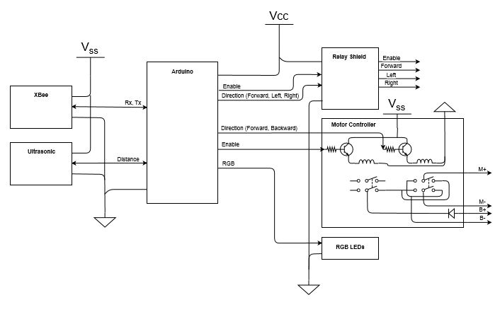
While writing this post, I stumbled upon an old block diagram I drew for Bubbles. Keeping it here for documentation purposes.
Firmware
The firmware is in a bit better shape than the hardware. I followed a similar firmware architecture to RoverBot with base drivers for servo, relay board, ultrasonic sensor, RGB LEDs, and motor controller all being wrapped into a higher level BubblesHardware object. The hardware object is a shared resource between teleoperated control and the autonomy state machine (again using roughly the same logic as RoverBot).
I am not going to deep dive into it here since I will be reworking it anyway in another post.
Check out the current firmware on GitHub here.
Software
Bubbles is built as three layers, shown below. It loosely follows the subsumption architecture popularized by Rodney Brooks, where each layer rides the one below it. Horse and rider is how I thought about it at the time.
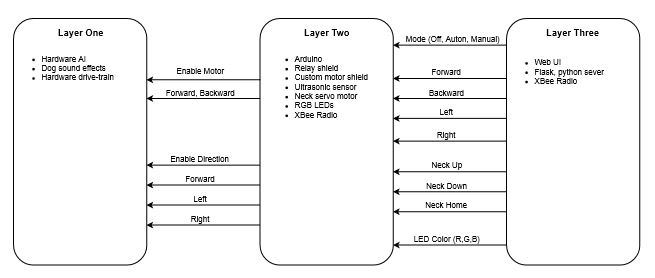
Layer one is the toy itself: the plastic body, the two motors and their gearboxes, and the factory electronics. I changed as little as possible here. The idea is to let the toy’s built-in behavior run the body while the layers above nudge it around using the same signals the leash remote used. The one real change is the tap on the drive motor control lines mentioned above, so the upper layers can get at movement directly.
Layer two is the Arduino stack: the Uno, the custom drive motor controller shield, a Seeedstudio ultrasonic sensor, a Seeedstudio relay shield, a generic RGB LED ring, a generic micro servo, and the XBee S1 radio (all in the block diagram above). This is where the autonomy state machine lives, and it drives layer one through the relays and the motor tap.
Layer three is the PC side, talking to the Arduino over the XBee link. The control app can switch layer two off entirely (so the toy hardware runs the body on its own), or put it in manual or autonomous mode. Manual mode is discrete commands: forward, backward, left, right, plus RGB LED color and head position. It is a Flask app in Python with an HTML / JavaScript UI.
The main problem right now is layer one ignoring movement commands after a while. The toy treats leash commands as suggestions. I think this is a protective feature left over from Bubbles’ toy days, so a kid who wandered off wouldn’t drain the batteries. My workaround is to drop any active relays for a moment and then re-assert them, so the toy sees a fresh button press. Future work is tuning that timing, plus power cycling Bubbles outright if he stops responding entirely.
Closing Thoughts
Bubbles was one of those projects that never quite went right. I think part of it was that I was still early in my engineering skillset and was stretching a bit. But the project itself also lacked a clear vision of what Bubbles should do. I still don’t know if I have a clear picture. Maybe it’s enough that the Bubbles project is re-engineered to be a decent platform for a PC controller / AI. There is also an old C# desktop app in the repo with an “emotional agent” in it that was more concept than implementation. Something to circle back on.
Watch for a new post on Bubbles in the future. My intent is to wrap up the hardware and firmware portions. Software will probably be a separate post way down the line.