Orion ~ A Robust Mobile Base
This is going to be a pretty short post as I don’t have much content for this bot.
Orion was a project I tackled in undergrad. I wanted to build a mobile base that could be used for experimentation (and I wanted it to be sturdy). Plus I had just gotten access to a makerspace and wanted an excuse to use it.
GitHub for this project is here. Note this project was never completed and never will be. I don’t even have the robot anymore (hopefully the underclassmen have made use of it).
Version One
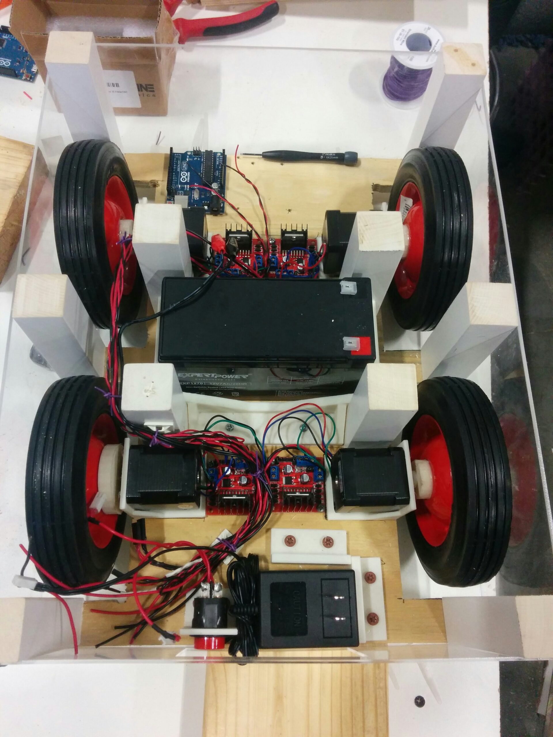
Orion V1 consisted of a chassis made of plywood / wood stock, and various small 3D printed parts.
Drivetrain was direct drive with four stepper motors (which was not the right call). Each stepper motor was driven by an off-the-shelf L298N motor controller board wired through to an Arduino Uno. Power was supplied via a 12V 7Ah SLA battery.
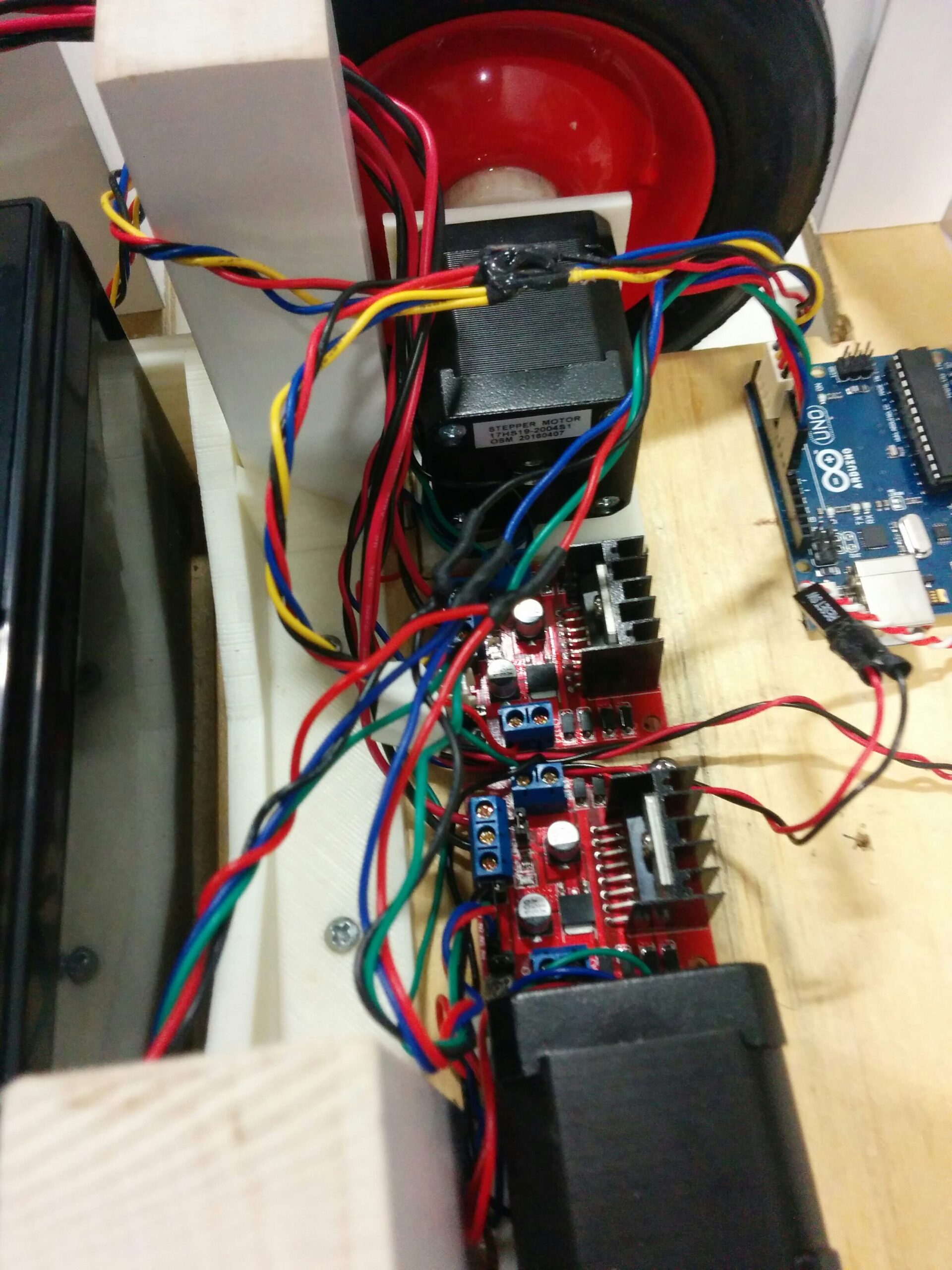
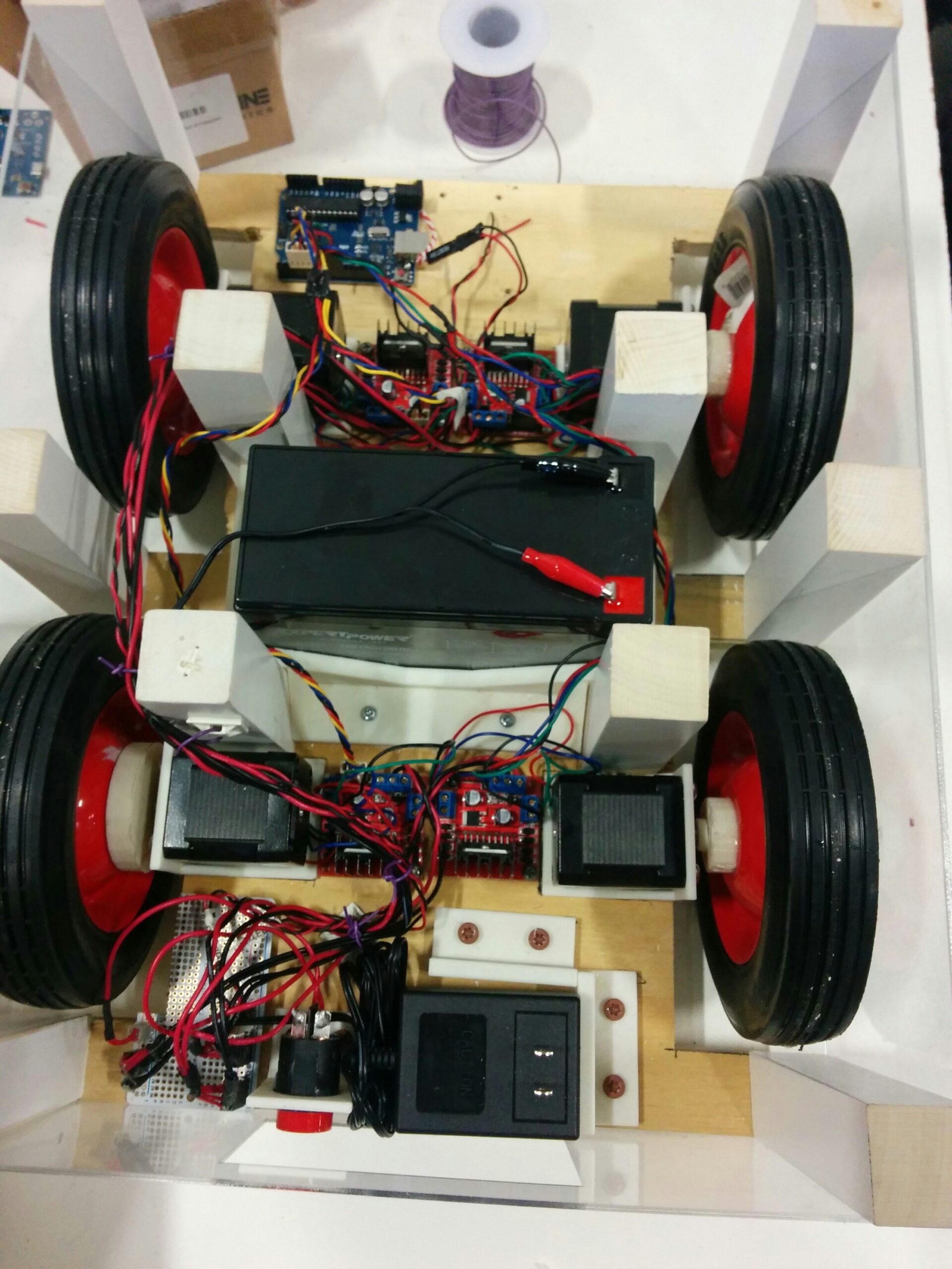
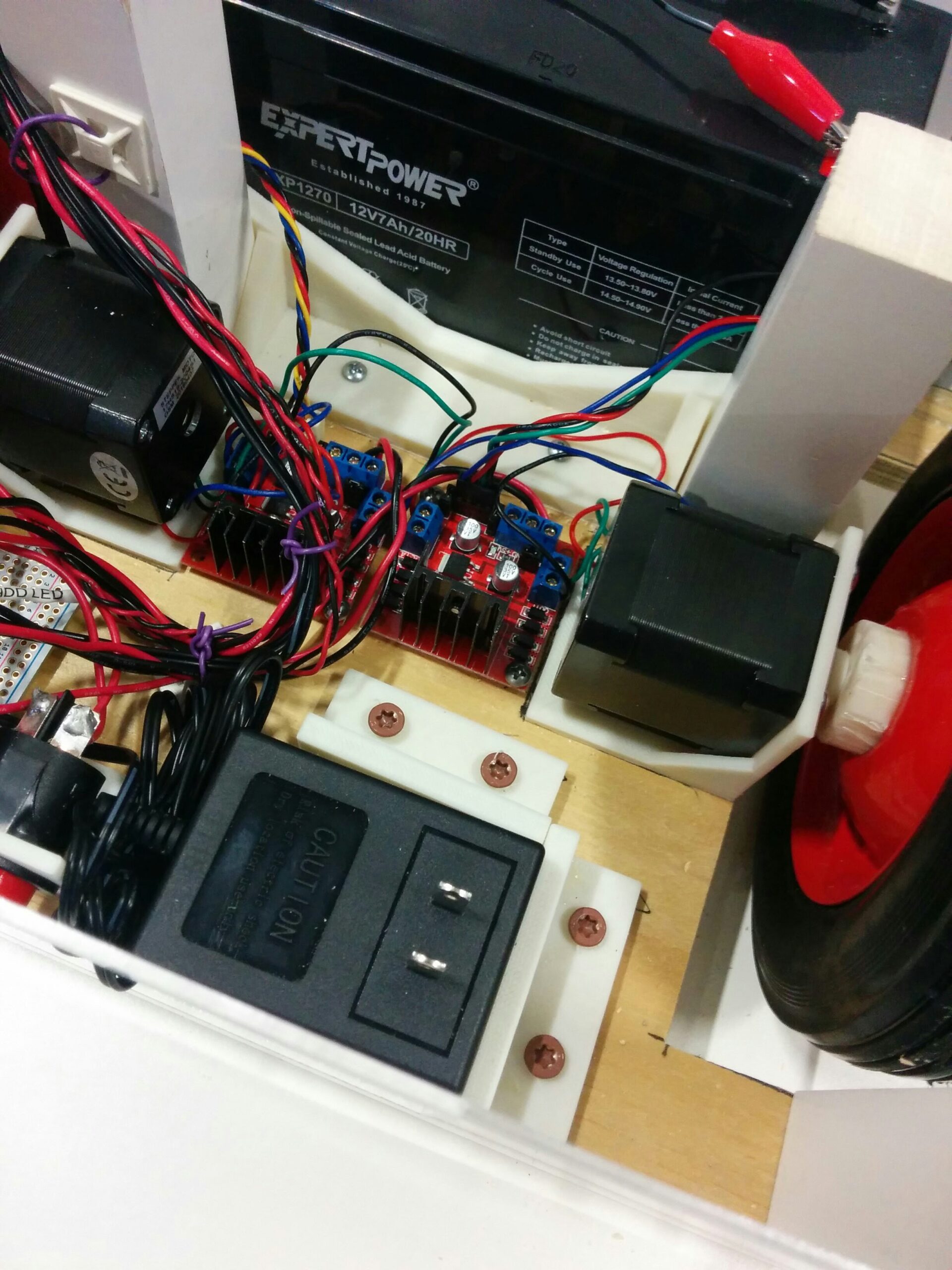
The main learning was from access to the 3D printer and the various small parts I had to CAD up. These included:
- Shaft adapters for mounting the wheels to the stepper motors
- Battery box for the SLA
- Right-angle brackets for the stepper motors, the SLA battery charger, and the e-stop button
All of it was modeled in Google SketchUp, which is not the right tool for the job.
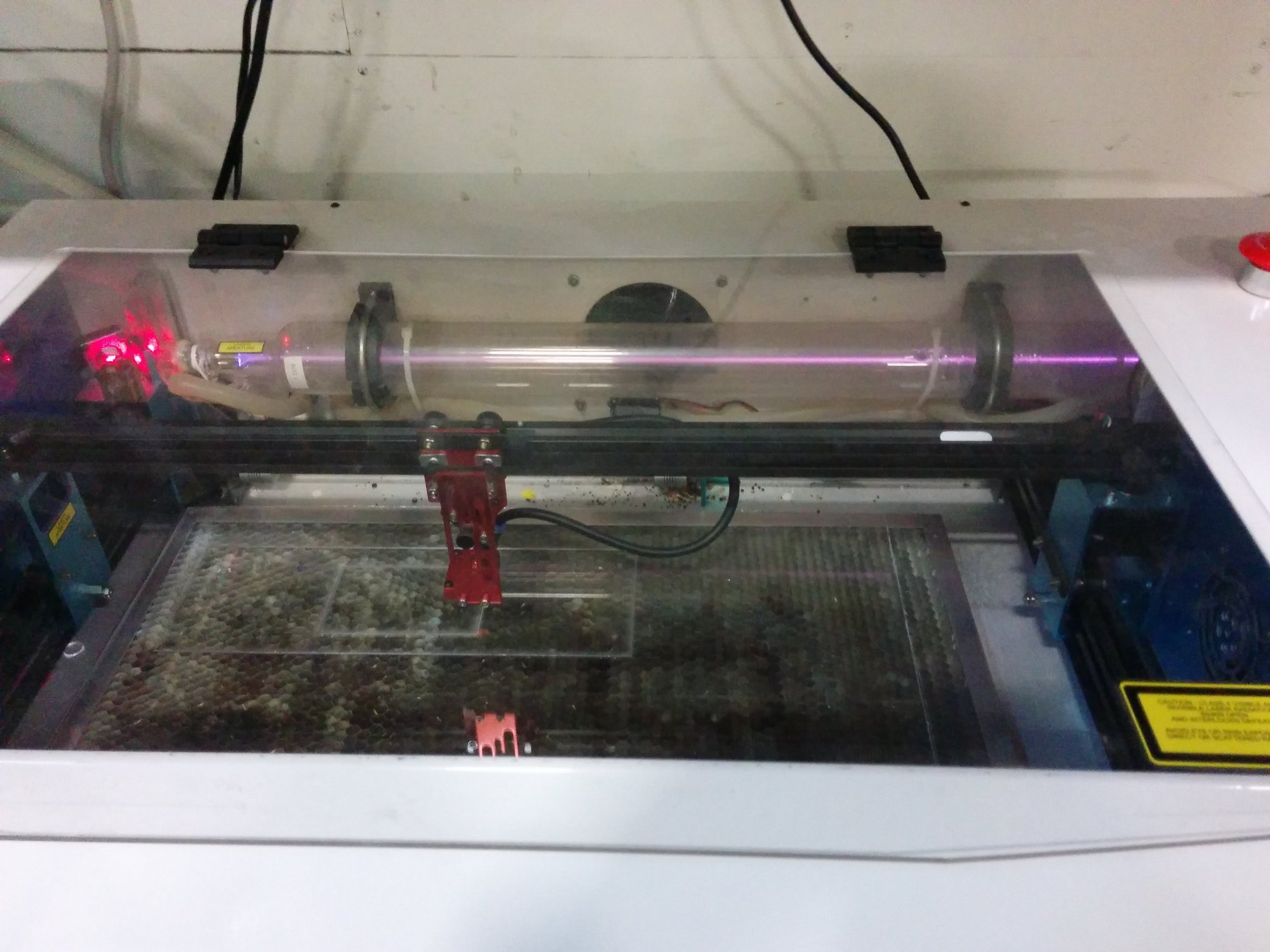
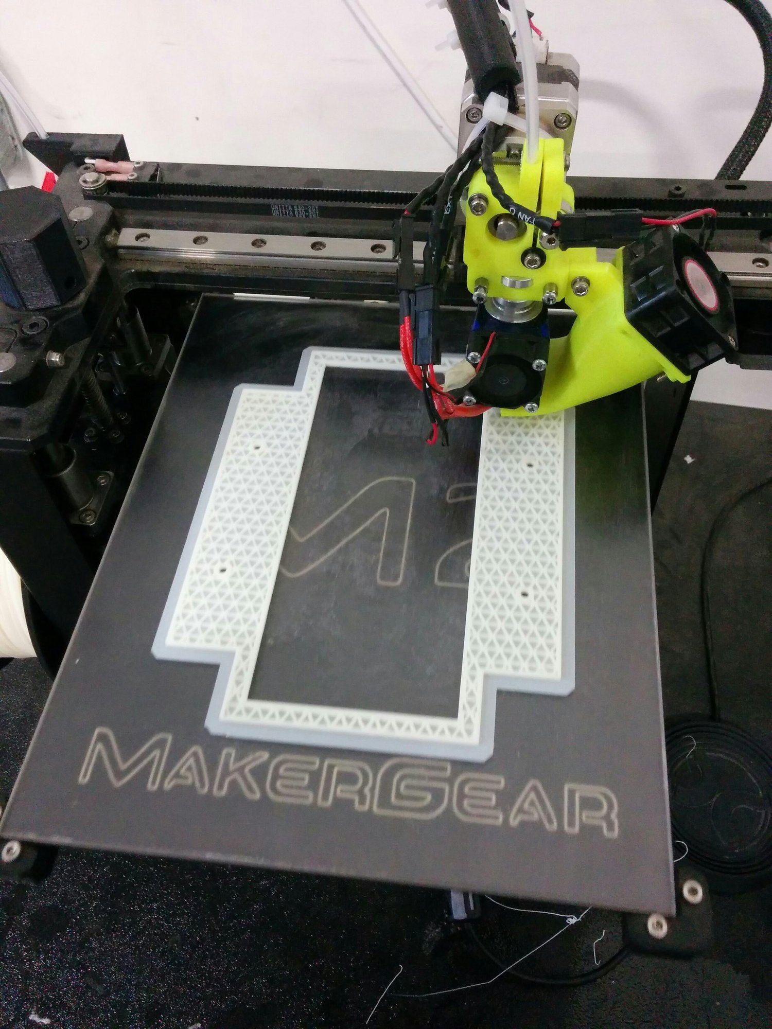
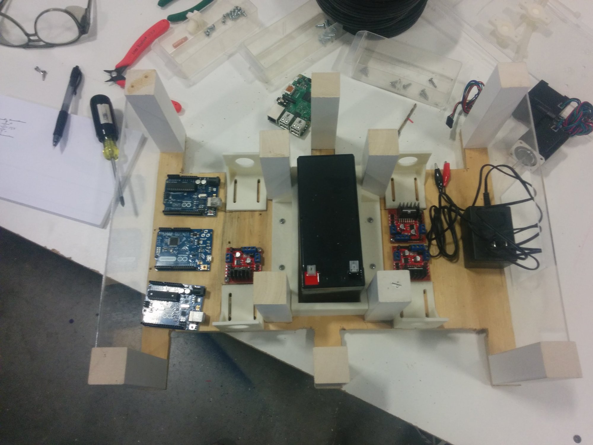
The main issue with this robot was the stepper motors got REALLY hot. It was a mistake to direct drive such a heavy robot with stepper motors. A stepper pulls its full rated current whenever it is energized, moving or not, so the motors were cooking even while the robot sat still. Their torque also drops off as speed goes up, which is backwards from what a heavy rolling base wants. The L298N boards did not help either since they don’t current limit like a proper stepper driver. I attempted to address this in version two.
Version Two
To address the stepper motor heating issue, I decided to switch them out for some VEX gearmotors and Victor SP motor controllers I had available. A DC gearmotor only draws what the load asks for and gets its torque from the gearbox, so it is a much better fit for pushing a heavy base around. I spent way too much time iterating and gluing the 3D printed mounting brackets to handle the torque of these motors. The drivetrain was now two motors instead of four, with each side having a direct drive wheel and a belt driven wheel. That meant more printed parts: pulleys, idlers, a spur gear, and a passive axle for the driven-by-belt side.
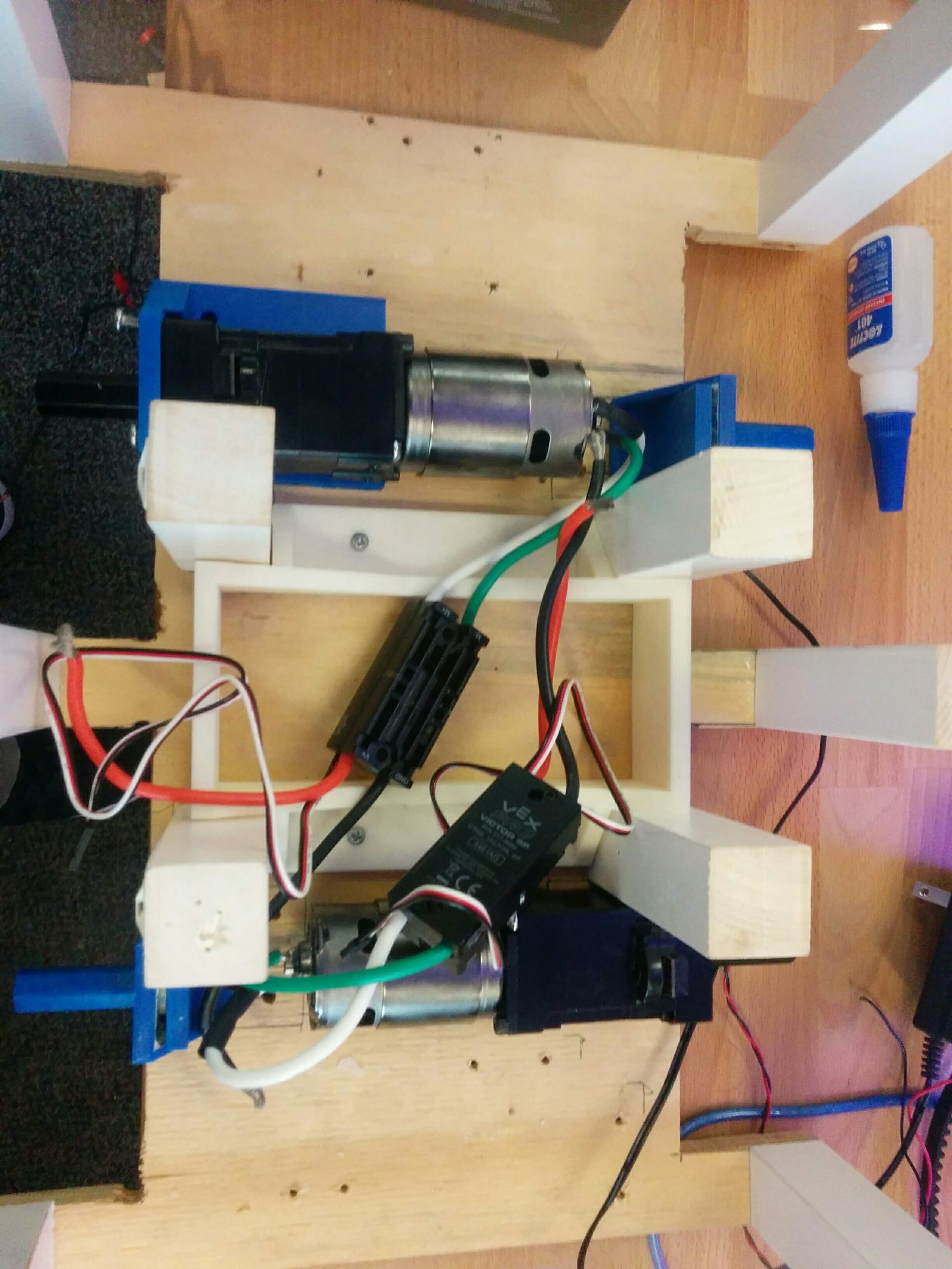
I was able to get this robot up to a drivable state (not that I ever documented it with a picture).
During this redesign, I switched out the controller from an Arduino Uno to an ESP8266 (my favorite microcontroller at the time). I wrote a simple website that acts as a virtual joystick sending control messages over a websocket to steer the robot. The firmware keeps a running average of the time between joystick messages and cuts the motors if it climbs past 75 ms, so a dropped phone connection stops the robot instead of sending it into a wall.
The firmware shares a lot of lineage with RoverBot and Bubbles; the three of them shared source code back and forth. It is in the Firmware folder of the same repo.
Final Thoughts
Building robots is a creative exercise and sometimes (or in my case, always) there are issues to work out. I spent way too much time learning lessons that looking back were obvious. But that is part of the journey to getting an understanding of what works and why.
Plus, I got to design some 3D printed parts and further developed my embedded system acumen. So win-win in my book.
I just wish I did a better job of documenting these formative projects back when I built them instead of nearly ten years later.