Triclops the Spinbot ~ Learning from Failure
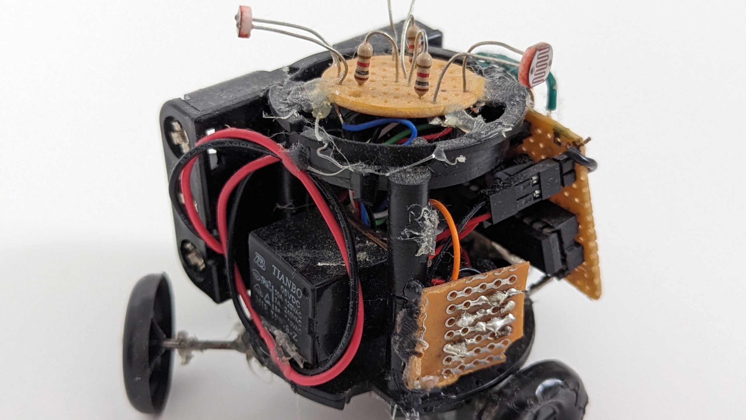
Triclops is another one of my incomplete projects. It started while I was a freshman at Milwaukee School of Engineering. My goal was to build a Spinbot: a single motor robot that modulates its speed to drift toward its target. Behaviorally the robot is designed as a Photovore where its target is the brightest light in a room.
The code is in my Simple-Hobby-Robot-Projects repository on GitHub. Note, it is not well maintained and probably never will be given this is an abandoned project.
Attempt #1
The following is my first attempt at making a Spinbot along with some of the old notes I wrote in the original blog (home-built-robotics).
This was during blog attempt #2, and Triclops was the first project I wrote up there.
So first, it has been a while since my last post. Partially because of my latest creation, and partially because of work and now college. So first a little about college, now a freshman at MSOE, going for a computer engineering degree. Classes start next week, it has been orientation all week. So hopefully I can somewhat retool this blog to also cater to my projects I will be doing at college.
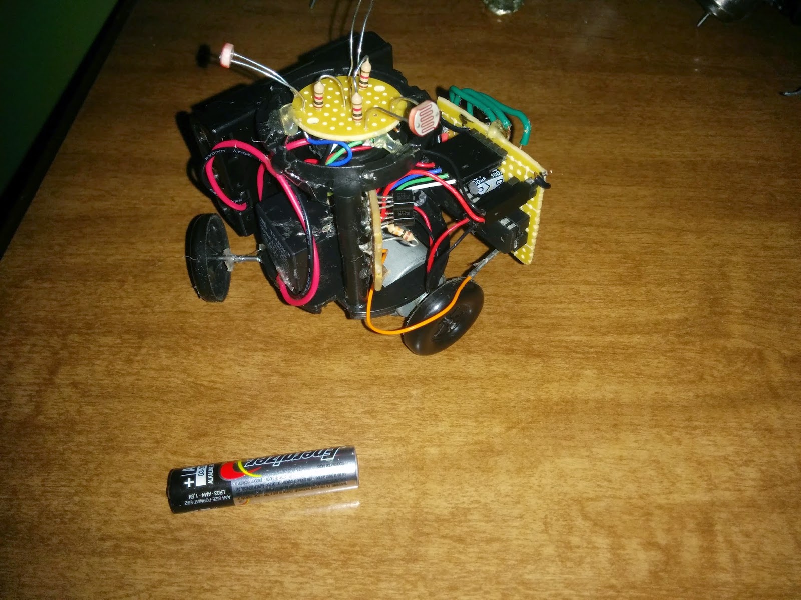
Triclops the Spinbot, attempt #1, with AAA battery for scale.
Triclops has one motor for output and thus can only spin in a circle. The radius of that circle depends on how fast the drive wheel is going, and that is the whole trick. Triclops rides on three wheels: one driven, with electrical tape wrapped around it for grip, and two free-spinning hard plastic wheels on fixed axles. The plastic wheels can only roll along their own line, so anything else means scrubbing sideways across the floor. At a crawl they hold and the drive wheel has to swing the whole chassis around them, which puts the center of rotation out near the free wheels and makes a wide circle. Get the drive wheel going fast enough and the plastic wheels lose their grip and skid, so the body spins around a point closer to its own center of mass and the circle tightens up. Pulsing the motor (a.k.a. PWM) lets the controller pick something between those two extremes, and dynamically adjusting it lets the robot modulate an arc and thereby drift in a target direction.
Below is a diagram demonstrating how I envision Spinbot behaving.

Sketch of example trajectory for Spinbot to a target (red cube). It needs to spin slower for arcs that approach the target and spin faster to stay around the same point for the next approach arc.
For sensory input I used three CdS photo-resistors that provide analog values for a PICAXE microcontroller. The PICAXE runs a variant of BASIC (different than the Parallax BOE-Bot BASIC) on top of a standard Microchip PIC microcontroller.
The following is the schematic capture for Triclops the Spinbot.
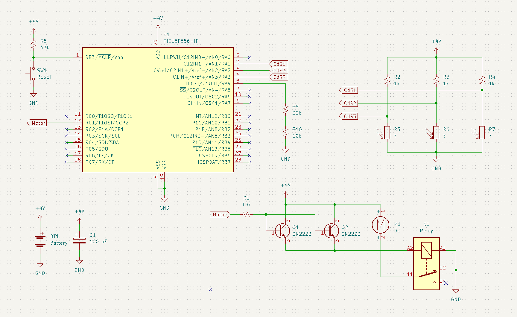
Worth noting a couple oddities in the circuit. The two resistors R9 and R10 in series were selected as the combined resistance was close to the target 35k ohms and I had these on hand. The parallel transistors Q1 and Q2 were to provide enough current to drive the relay I salvaged from an old toy.
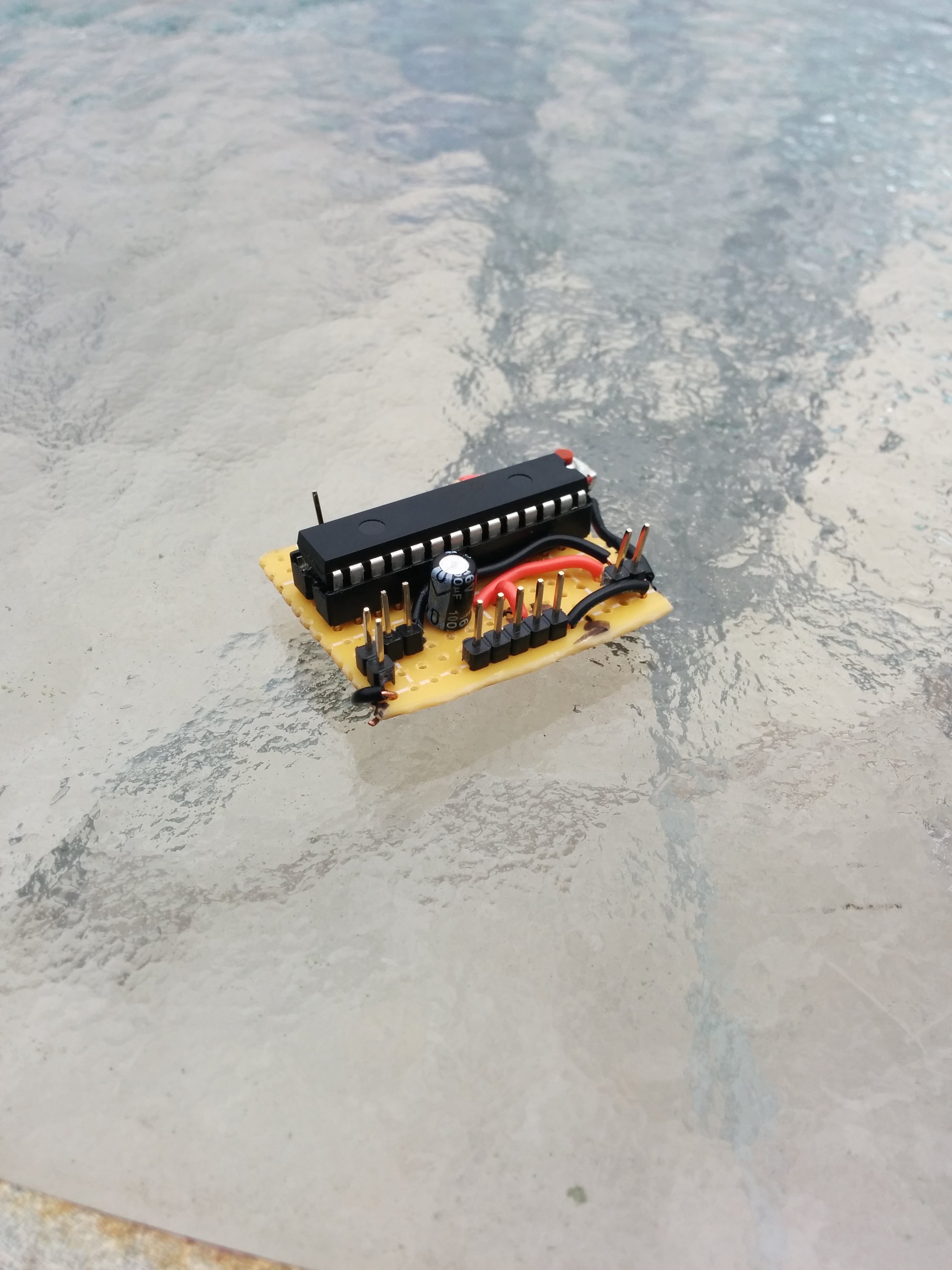
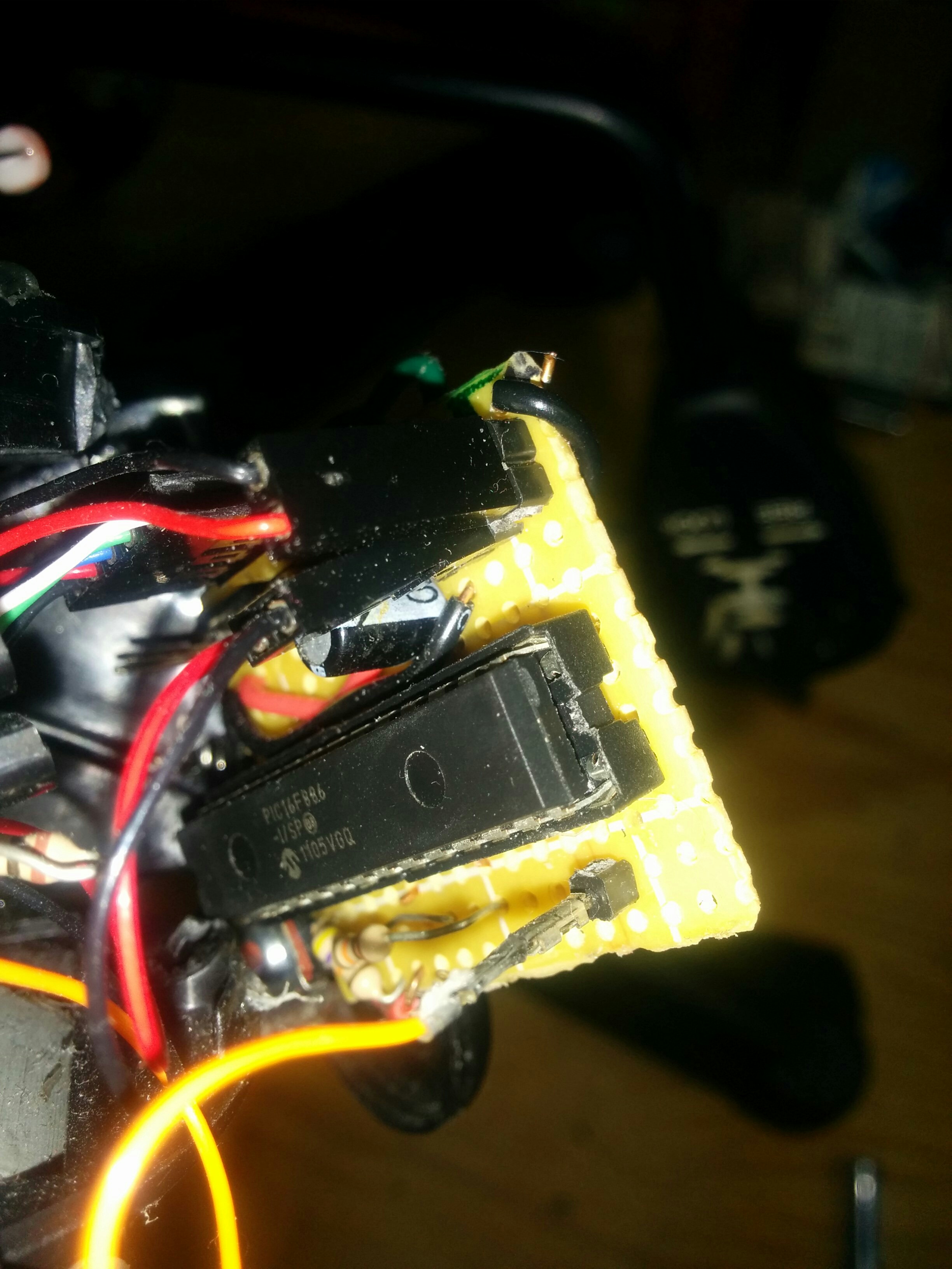
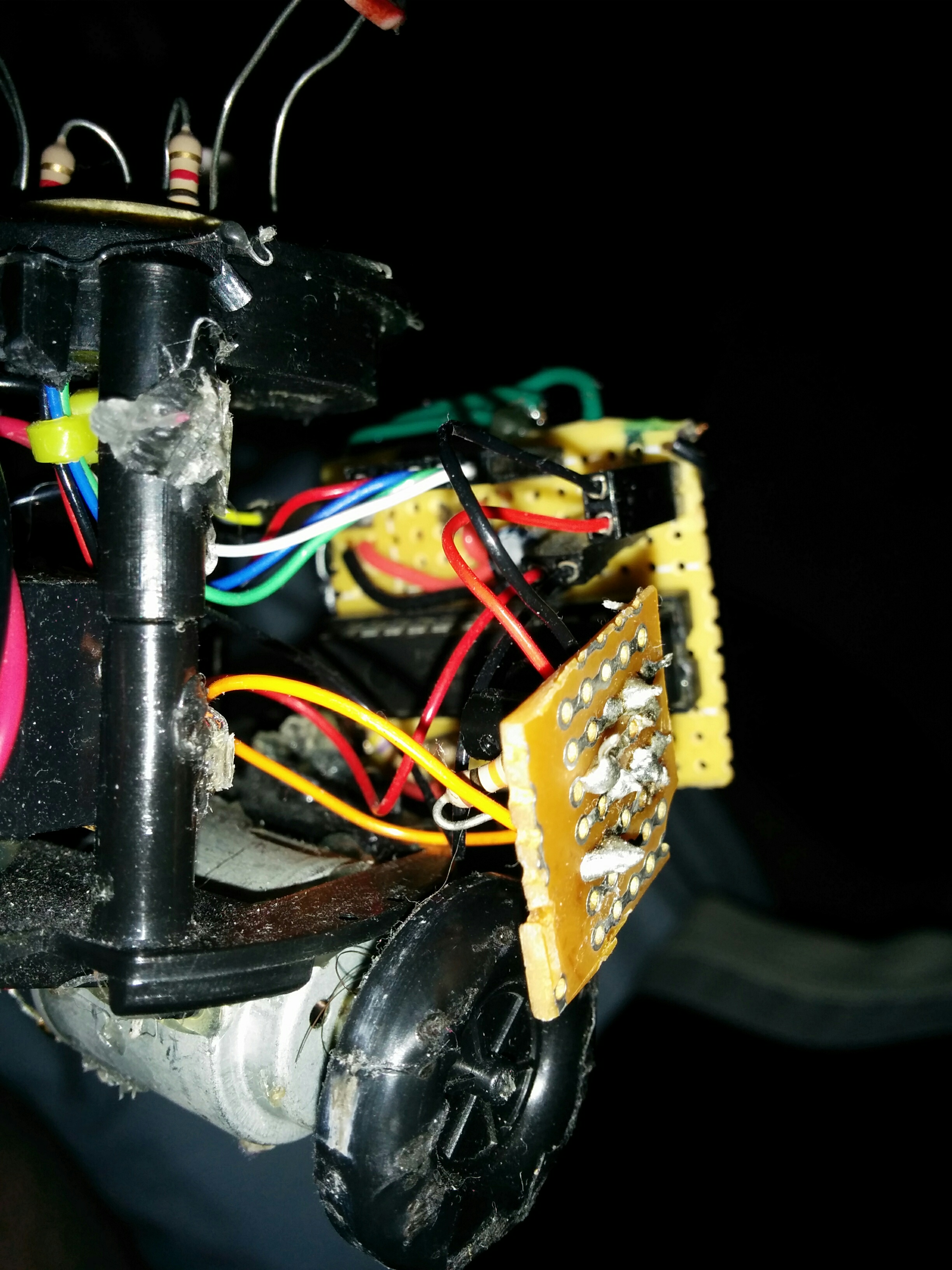
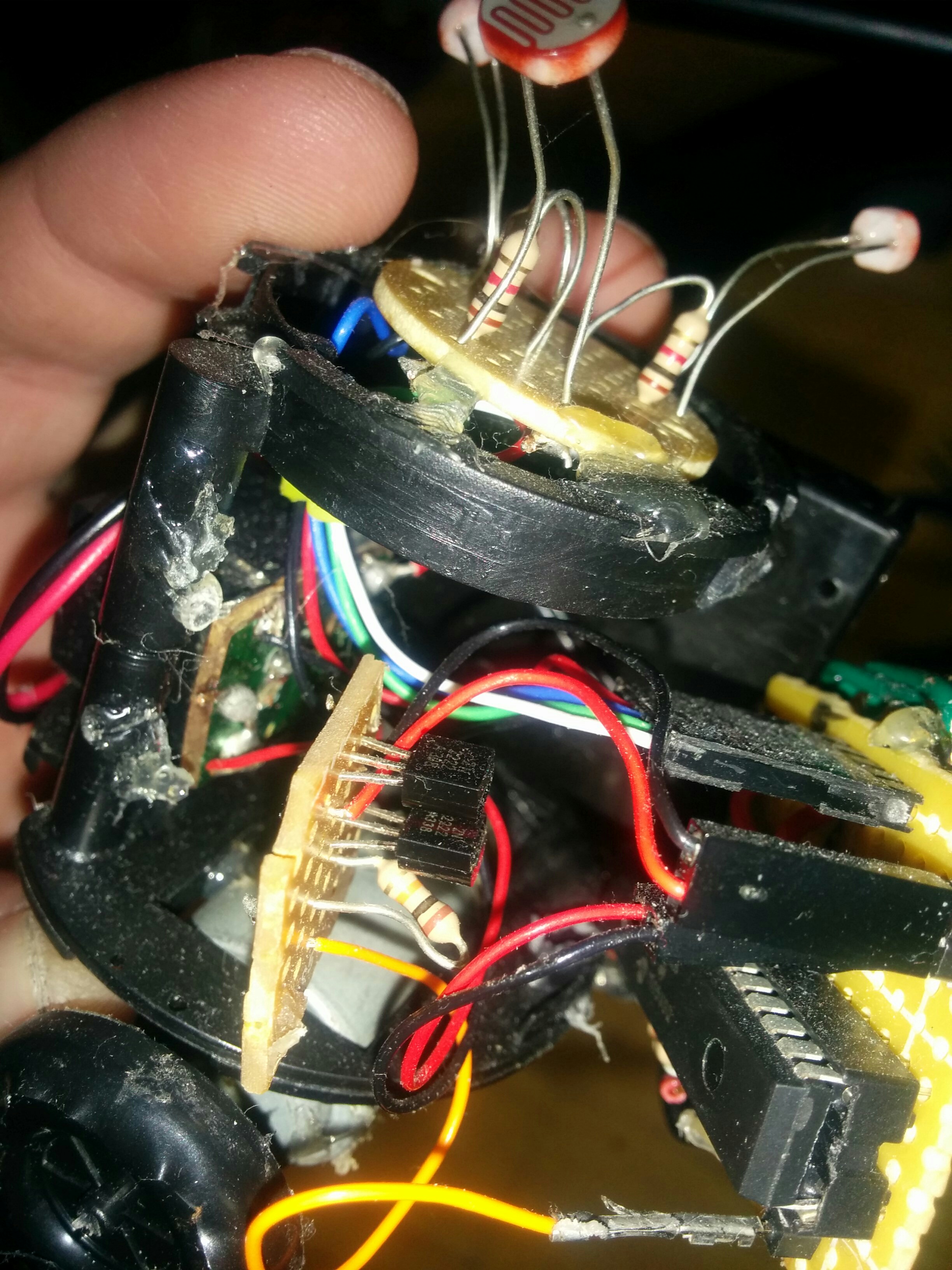
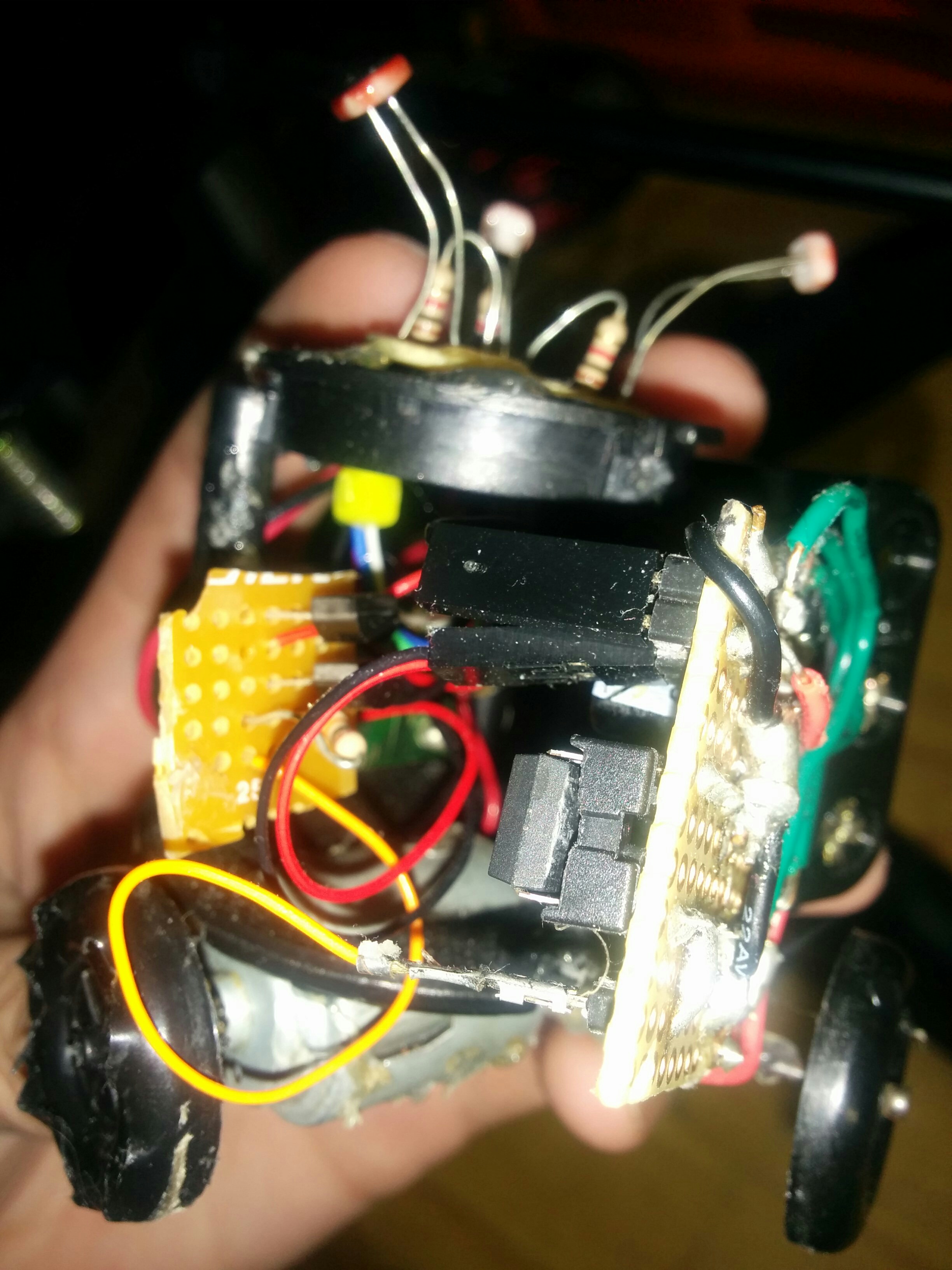
I soldered the circuit on some spare protoboard. It was a bit less of a rat’s nest than some of my older robots but not by much.
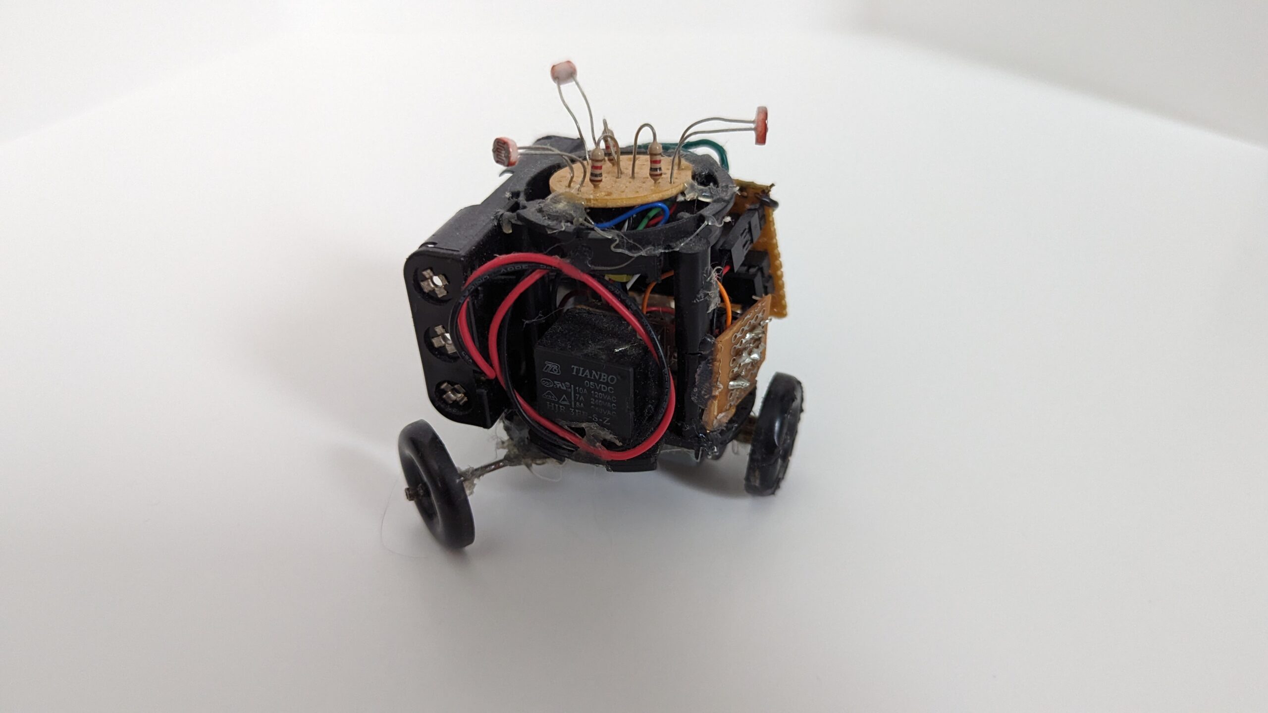
Mechanically, it was a mess of hot glue and salvaged parts. The motor and wheels were from old toys. Note, I had to use electrical tape on the drive wheel as the “rubber” to increase friction. The other two wheels stayed bare plastic, which is what lets them skid the way I described above. The chassis was the base of an old solar flower decoration that belonged to my great grandmother. When it broke I cannibalized it. The flower and its solar engine became a very early version of my BEAM robot SymFlower, and the base sat in the parts bin until it became Triclops.

The code (magic) of the robot is how the three sensors are able to control that one motor so that it tracks the brightest light source. I had just learned what a perceptron was and wanted an excuse to try one, so instead of working out the math myself I used a single perceptron with a step activation to decide when to fire the motor. Effectively a bang-bang closed-loop control policy.
I hand-tuned the weights in Microsoft Excel. I assumed a single ideal light source, which as the robot spins looks like the same sinewave to each sensor, phase shifted 120 degrees apart. When the sinewave is negative the sensor reads noise.
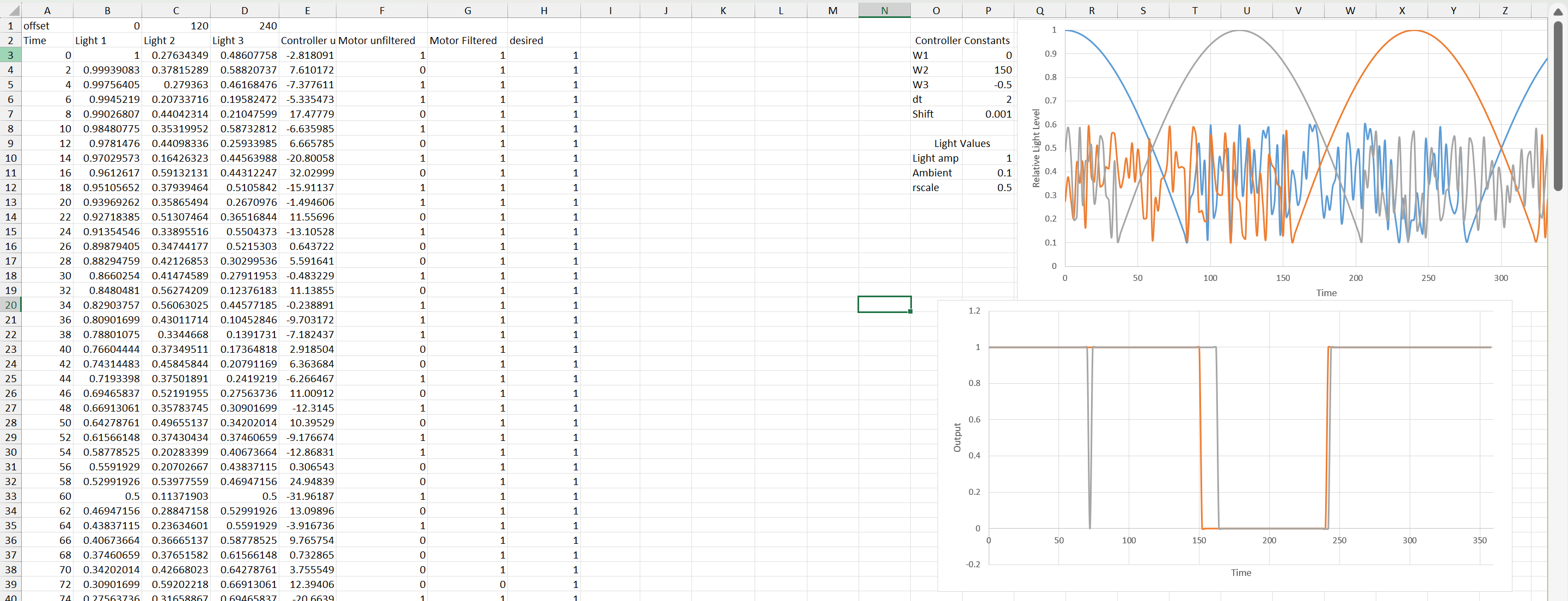
Close-up on the input graph.
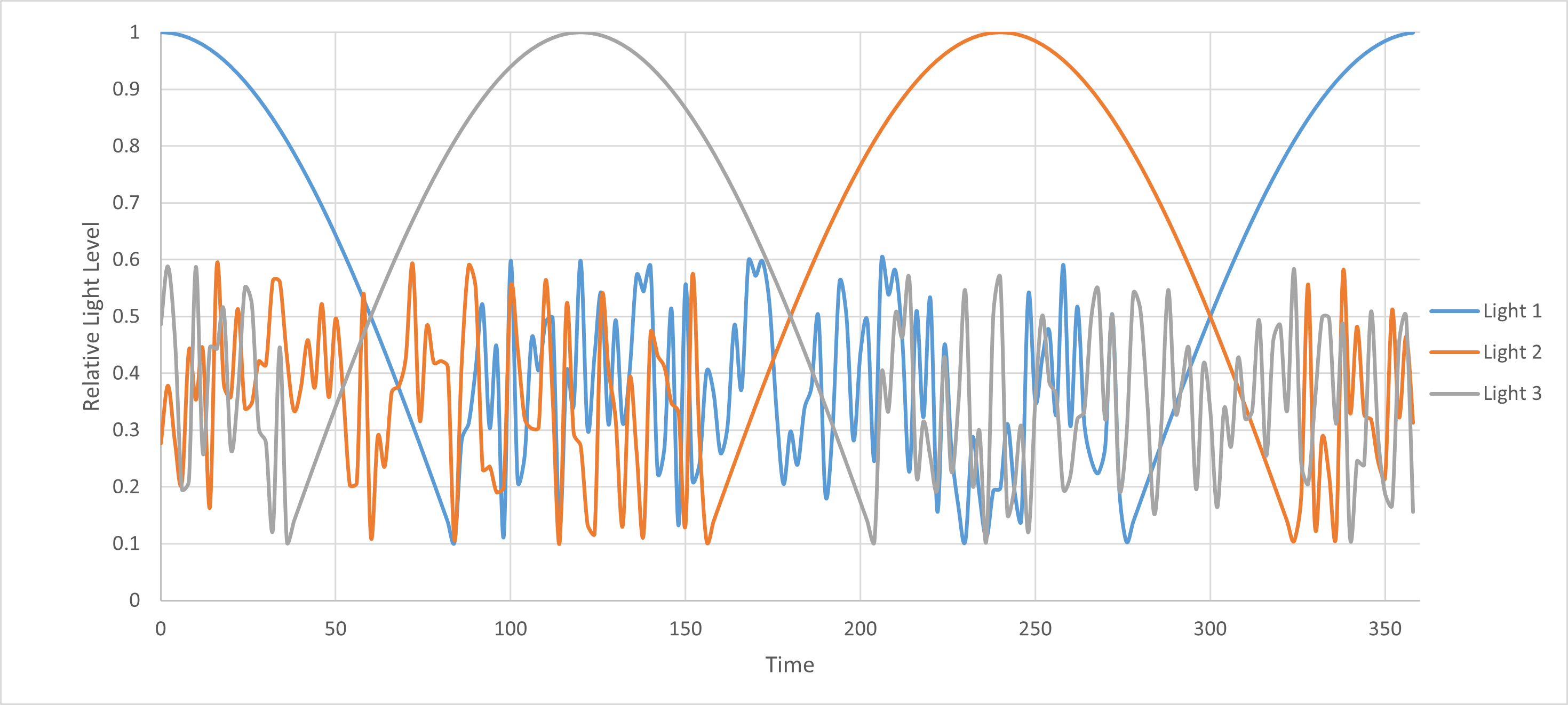
And the output graph with ideal and actual output.
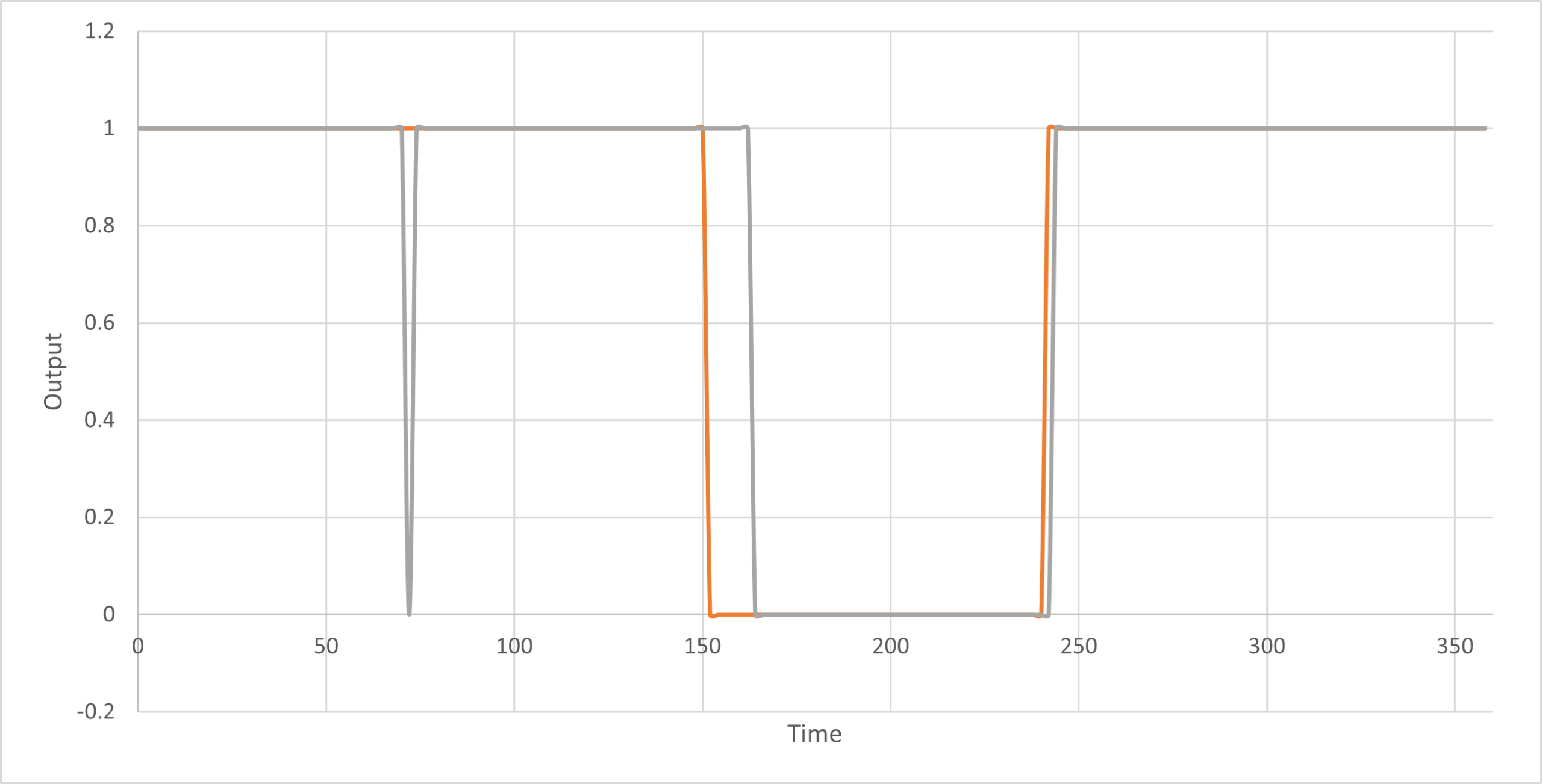
This would have been fairly simple to do on an Arduino, but the PICAXE microcontroller I selected does not natively support floating point values (which is how neurons are canonically presented in textbooks). So freshman me thought, what about modulus? It’s when you divide two values and keep the remainder as the output. I rationalized that decimal values between zero and one are near equivalent to the remainder between 0 and 65535.
That rationalization is where I went wrong. What the code below actually does is integer scaling: multiply the sensor percentages by big integer weights, add them up, divide by 400. There is no modulus operator anywhere. The “modulus” is just the PICAXE’s 16-bit word variables wrapping around at 65535, and that happens in two places. -1000 * sense3 wraps to a large positive number, and the other three terms can pass 65535 on their own (64900 + 13100 + 15000). On top of that, IF neuronSum > 0 on an unsigned word is true for anything but zero, so the motor fires unless the wrapped sum happens to land under 400. So the neuron I tuned in Excel is not really the one that ran on the robot.
Anyway, here is the code.
'set variables for reading adc cds cells, and neural model memory
symbol sense1 = w1
symbol sense2 = w2
symbol sense3 = w3
symbol bias = w4
symbol neuronSum = w5

symbol cds1 = 1
symbol cds2 = 3
symbol cds3 = 2


'models a single neuron as described above taht was trained to
'determine whether to turn on or off the motor in regards to
'the current light level
main:
	'get analog values from cds cells as byte
	readadc cds1, sense1
	readadc cds2, sense2
	readadc cds3, sense3

	'convert from byte representation to precent
	let sense1 = sense1 * 100 / 255
	let sense2 = sense2 * 100 / 255
	let sense3 = sense3 * 100 / 255

	'assign weights to inputs
	let sense1 = sense1 * 649
	let sense2 = sense2 * 131
	let sense3 = -1000 * sense3
	let bias = 15000

	'sum weights and apply activation function
	let neuronSum = sense1 + sense2 + sense3 + bias
	let neuronSum = neuronSum / 400

	'if past threshold then trigger motor
	IF neuronSum > 0 THEN
		high portc 1
	ELSE
		low portc 1
	ENDIF

	pause 5

	goto main
The first version of the firmware was unstable. The robot kept ramping up its speed, so I tried a lot of things to calm it down, including feeding the previous motor output back into the sum as a negative weight so it would back off. None of those versions survived; the code above is what ended up archived. Another casualty of a half-finished project.
So now I am in the tuning stage. I plan on taking a video of it once I go back home.
(there never was a video and not much tuning)
Result of attempt #1 was a robot that could spin in a circle and sort of drift but definitely not smart enough to be a proper Photovore. The controller needs more than one neuron, but the bigger problem was the drive. The code toggles the relay every 5 ms as if it were a PWM output. That relay came out of an old toy and a mechanical relay cannot switch anywhere near that fast. In practice the motor was either on or off, so the fine speed control (that the whole Spinbot idea depends on) was never really there. Lesson learned, the relay could not switch fast enough.
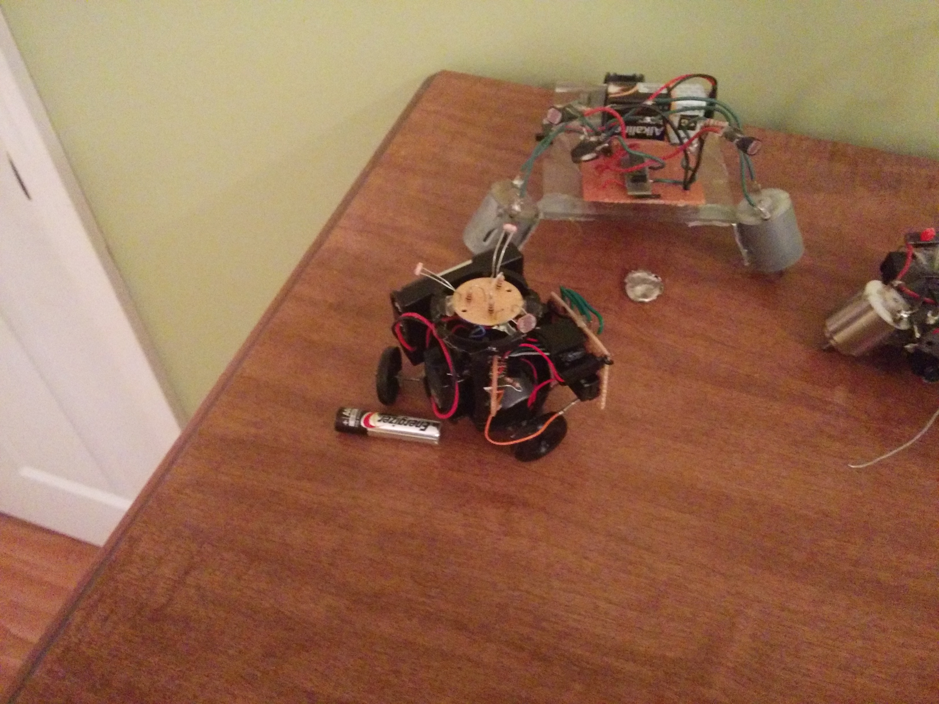
Triclops alongside some of my other robots: NoBB (behind) and Beetle (right).
Attempt #2
The summer before grad school at the University of Wisconsin-Madison, I revisited this project with a focus on improving the neural network controller.
Simulation
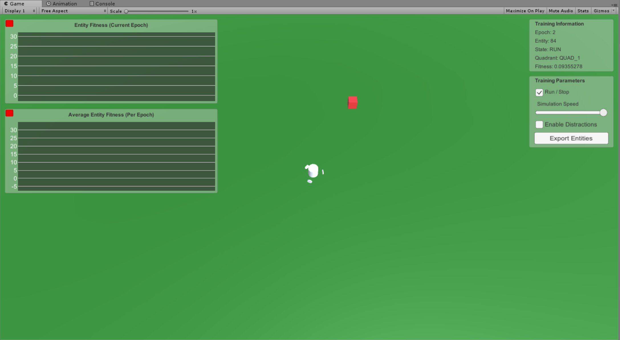
I decided to build a simulation in Unity (Game Engine) to model the rotation physics. The simulation consists of the robot model, ground plane, and a target cube.
The robot was modeled with three wheels providing friction between it and the ground plane, with one of the wheels being the drive wheel. The drive wheel applied a force against the ground plane, thereby propelling the robot. Gravity was set to default. A simple script could then modulate the force and thereby induce variable arc radii.
Next was designing the target and sense system (represented as a red cube). The cube itself is a non-interactable object that is randomly placed in one of the quadrants relative to the robot (the robot always starts at origin). The robot has “sensors” above each wheel that detect how bright the cube is. Brightness is a function of the angle from center and distance from the sensor. Noise can also optionally be applied to improve the real-ness of the reading.
Lastly, as shown in the image, I built a simple UI to help diagnose the training, though the fitness graphs seem to have broken sometime between 2018 and 2025.
Controller & Training Algorithm
With the simulation setup out of the way, let’s discuss the controller.
The controller is a standard shallow neural network with an input layer, hidden layer, and output layer.
- Input Layer = 9
- Input layer is a bit larger than one would expect given there are three sensor inputs. Instead of just piping in the current sensor readings, each sensor has a current value and two previous values. This gives the network a bit of memory about its environment.
- Hidden Layer = 5
- Hidden layer was five neurons after some manual tweaking. I wanted to keep this number lower since it would be implemented on the PICAXE.
- Output Layer = 1
- Output layer being one neuron makes sense. The motor is either on or off.
I decided to use an evolutionary algorithm to train the neural network. At its simplest, it’s a collection of neural networks that successively get selected by their fitness.
A couple things to keep in mind:
- Each neural network can be represented as a string of weights; this is its genetic code
- Neural networks can breed in pairs; the genetic code is a combination of the two parents
- The genetic code also has a chance for random mutations during breeding
Testing neural networks for fitness happens within an epoch (a generation of neural networks). Each network gets four trials, one per quadrant, with the target dropped at a random spot 8 to 12 units out from where the robot starts. A trial ends when the robot touches the target or when 30 seconds run out. If it touched the target, the trial scores 1 plus a bonus for the time left over, scaled by how far away the target started, so a quick trip to a far target scores best. If it timed out, the trial scores 1 over the remaining distance to the target, which tops out at 1. The four trial scores are added together for the network’s fitness.
After an epoch (set to 100 neural networks), there is a subset that passes along directly into the next epoch (10 best performing nets). The other 90 are children: each of the top nine is crossed with each of the top ten and then mutated. Note, the first epoch is special since all networks are randomly generated. The hope is eventually, there will be an epoch with a neural network suitable for Spinbot’s controller.
I took heavy inspiration from this YouTube tutorial by Underpower Jet: Tutorial On Programming An Evolving Neural Network In C# w/ Unity3D. Highly recommend watching for a better explanation.
Results
After setting up the simulation and writing the neural network training code, I was able to collect some interesting models. These were exported into a JSON file for further analysis. That analysis never happened. Classes started for the fall term and this is where attempt #2 stalled.
Qualitatively, the simulation showed the Spinbot concept works, at least in simulation, and that the general training plan was sound. I observed several networks that were able to modulate their arcs to hit targets in multiple quadrants. I doubt those models would have ported straight onto the PICAXE though. The simulated sensors and motor are much cleaner than the real ones, and the real motor was still hanging off that relay.
Photoshoot
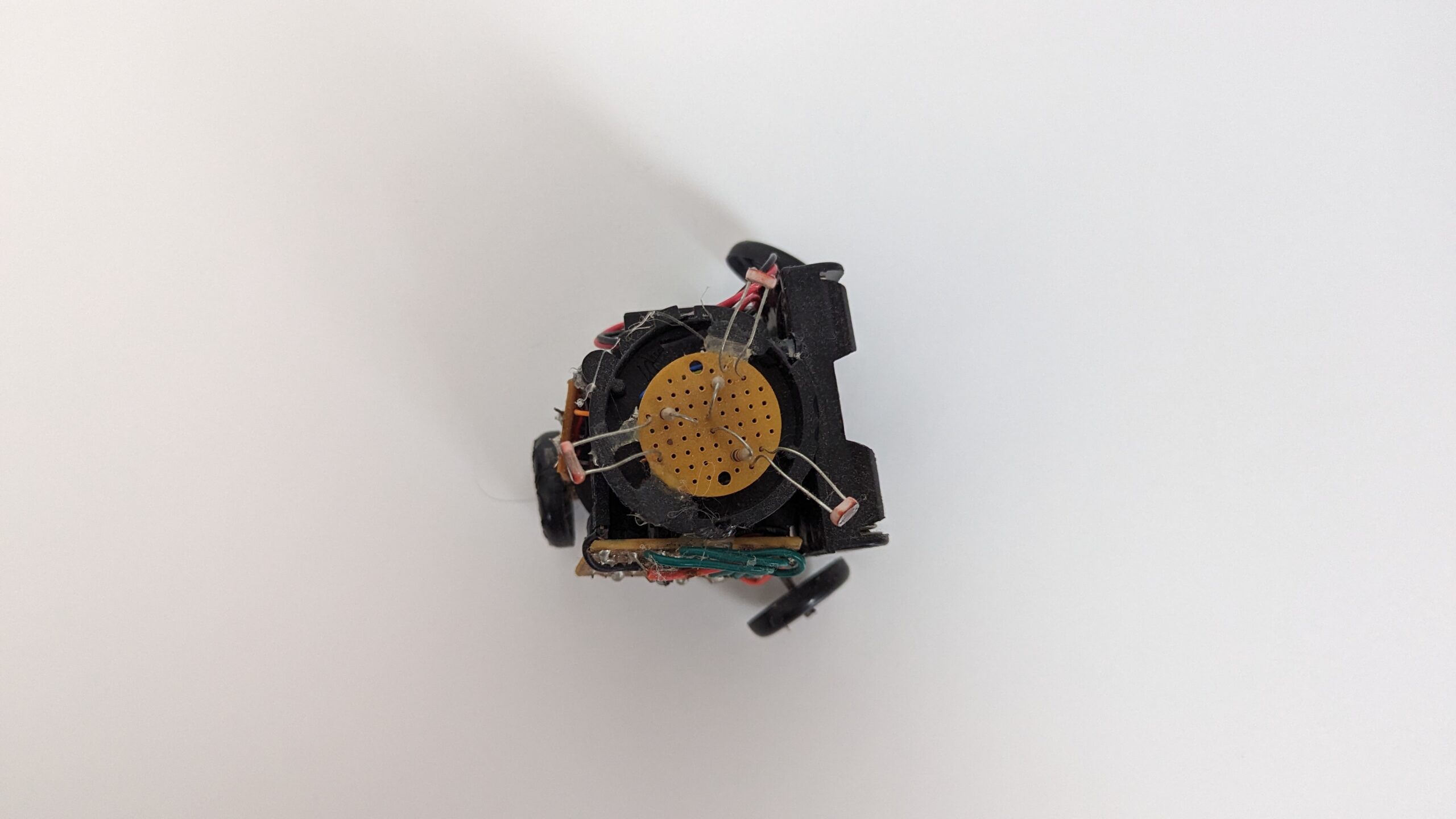
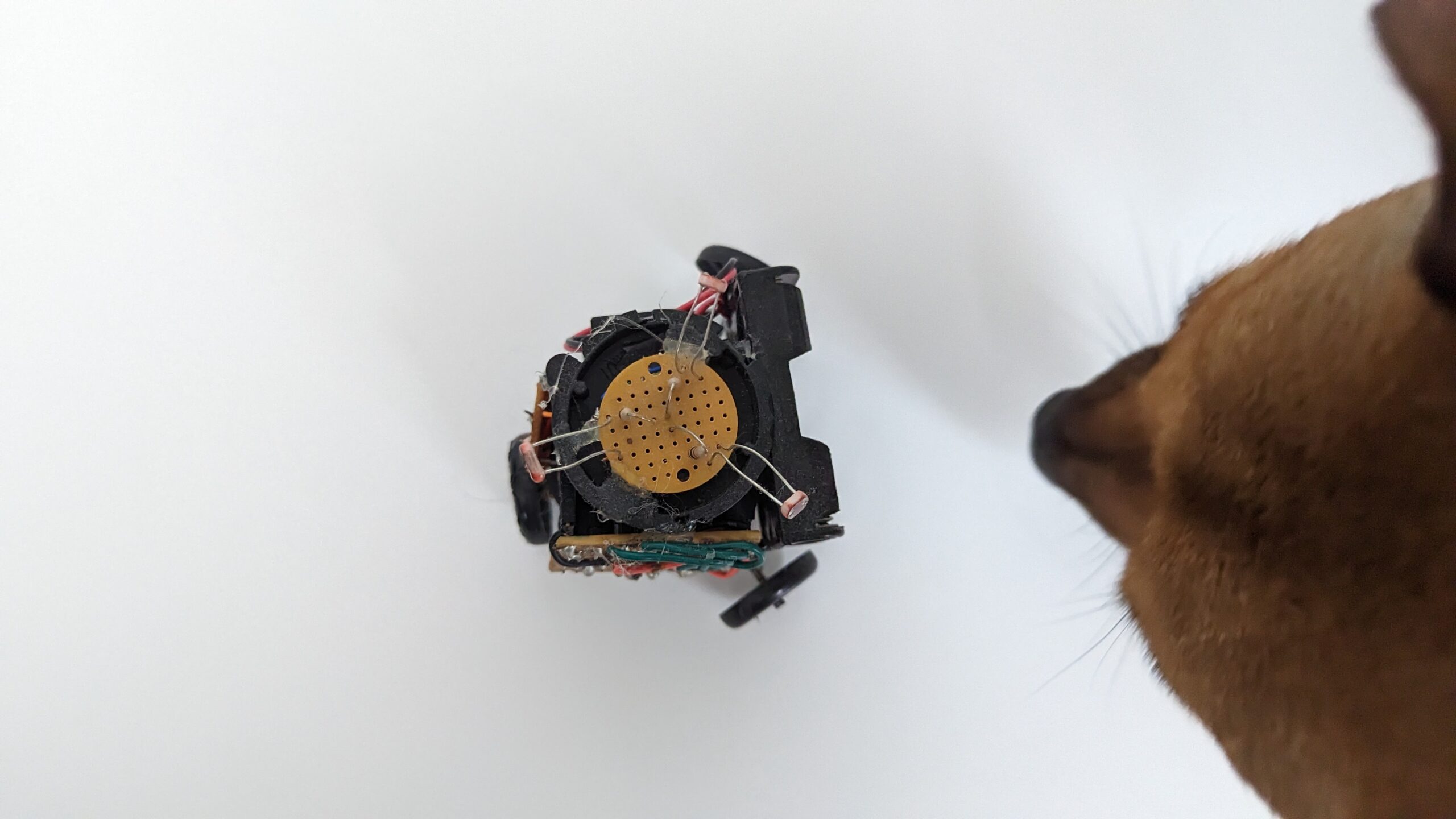
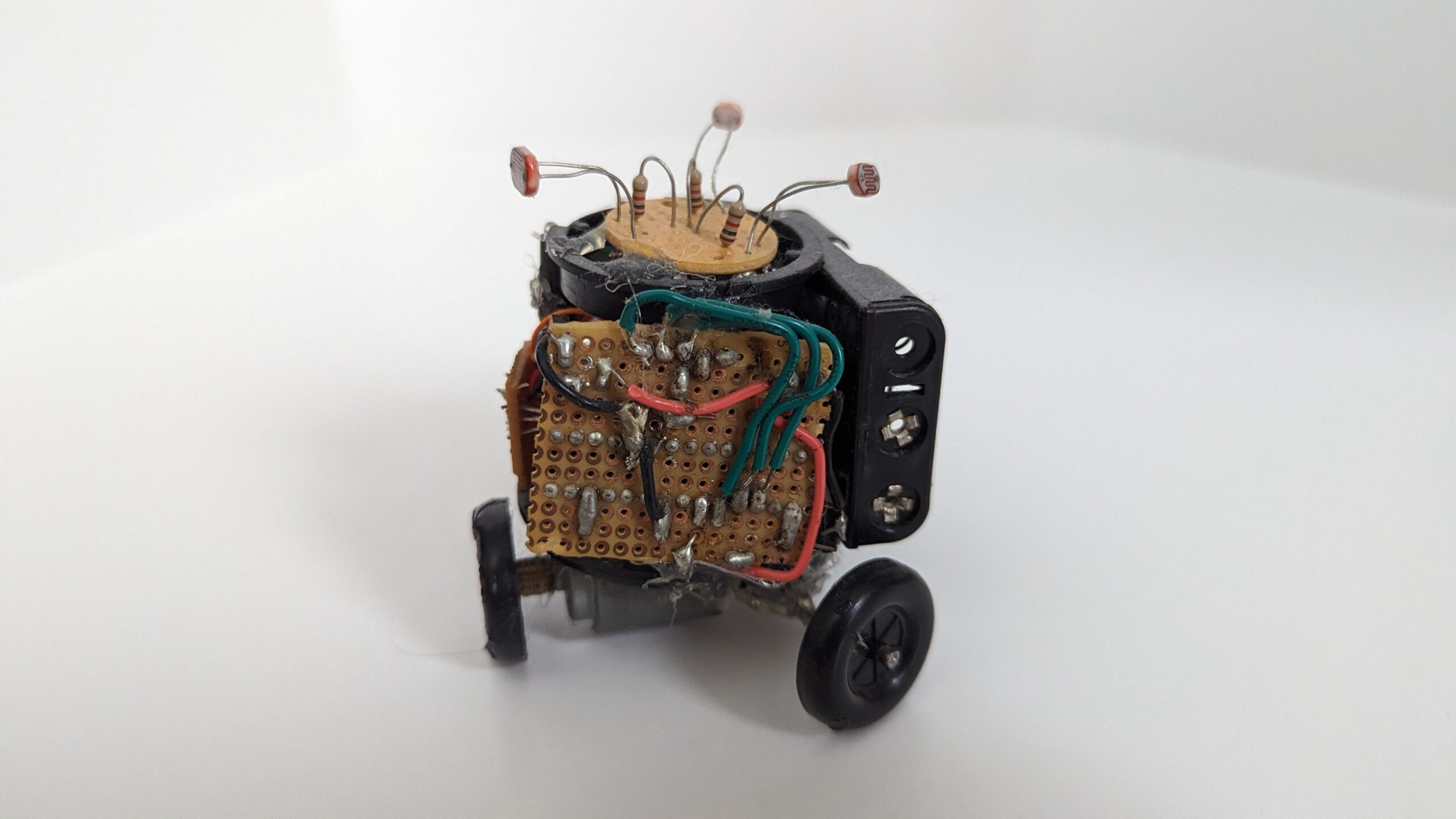
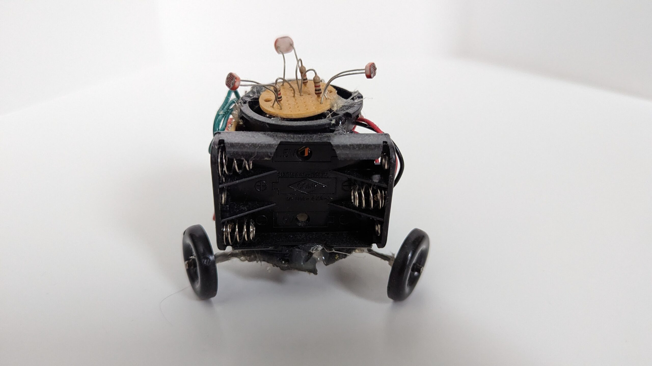
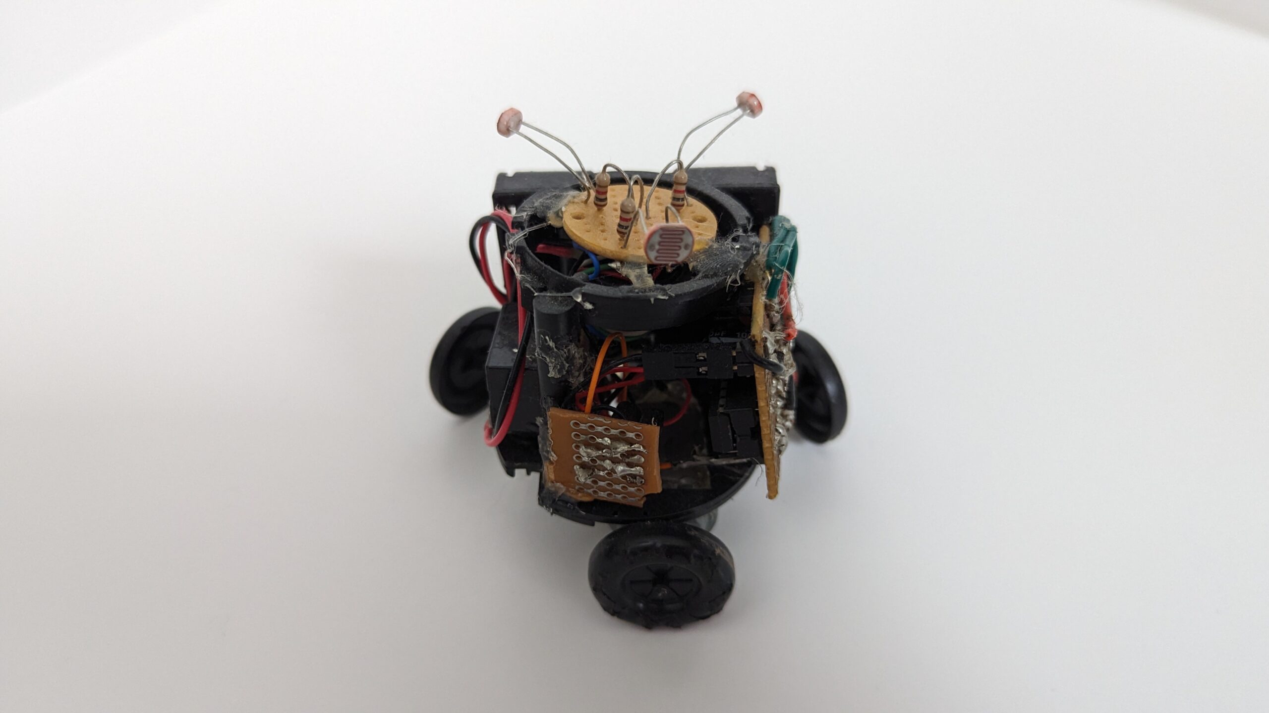
I did a photoshoot with some of my robots. Here is the gallery for Triclops the Spinbot.
Closing Thoughts
Projects can be started with the best of intentions but they don’t always lead to a complete (or near complete) robot. Sometimes it’s the lessons learned that are the takeaway. In this case the neural network & evolutionary training algorithms I learned were useful for future projects. Rereading my old notes was a little embarrassing (freshman me was very confident about that modulus idea) but the mistakes are the part I actually learned from.
I would like to come back to the Spinbot idea. Here is what I would do for attempt #3.
-
Build a new hardware platform that is easier to configure and control. The microcontroller should be modern and have wireless onboard, perhaps an ESP32 if we want a small project or a Raspberry Pi if we want to do something fancy. Regardless, being able to send firmware updates / model updates wirelessly would be rather important for tuning the controller. Motor control should be a standard PWM driven module instead of a relay.
-
Choose a coordinate frame. Light sensors are interesting due to their low resolution. When the robot is spinning, the timing of the peak gives a bearing to the brightest light, and the height of the peak gives a rough range if you assume a point source. So they give a local polar coordinate frame, more or less. Alternatively, if we went with a cartesian coordinate frame it would be natural to steer the robot with a joystick or define navigation missions. This requires some way of knowing where the robot is, orientation-wise, relative to its original position (or a predefined room coordinate). A gyroscope on its own drifts, so this is probably a gyro plus a compass (and perhaps an accelerometer) fused through a Kalman filter, if we can sample fast enough. Or we could go more exotic with visual-inertial odometry.
-
Train a control policy. I like the direction I started down with the Unity simulation and neural network & evolutionary algorithm, though a more straightforward way to create a control policy for this robot might be reinforcement learning. Either way, final tuning of the algorithm needs to happen on hardware, and more complex simulation scenarios are probably needed to reduce the likelihood of overfitting (such as to the quadrant task).
To quote myself from the old draft of this post:
Well if any of you have comment out there in the wide web internet realm please drop me a comment. Till the next post be safe and go out and build something! :p