Next Steps with Robotics Kits ~ Parallax BOE-Bot
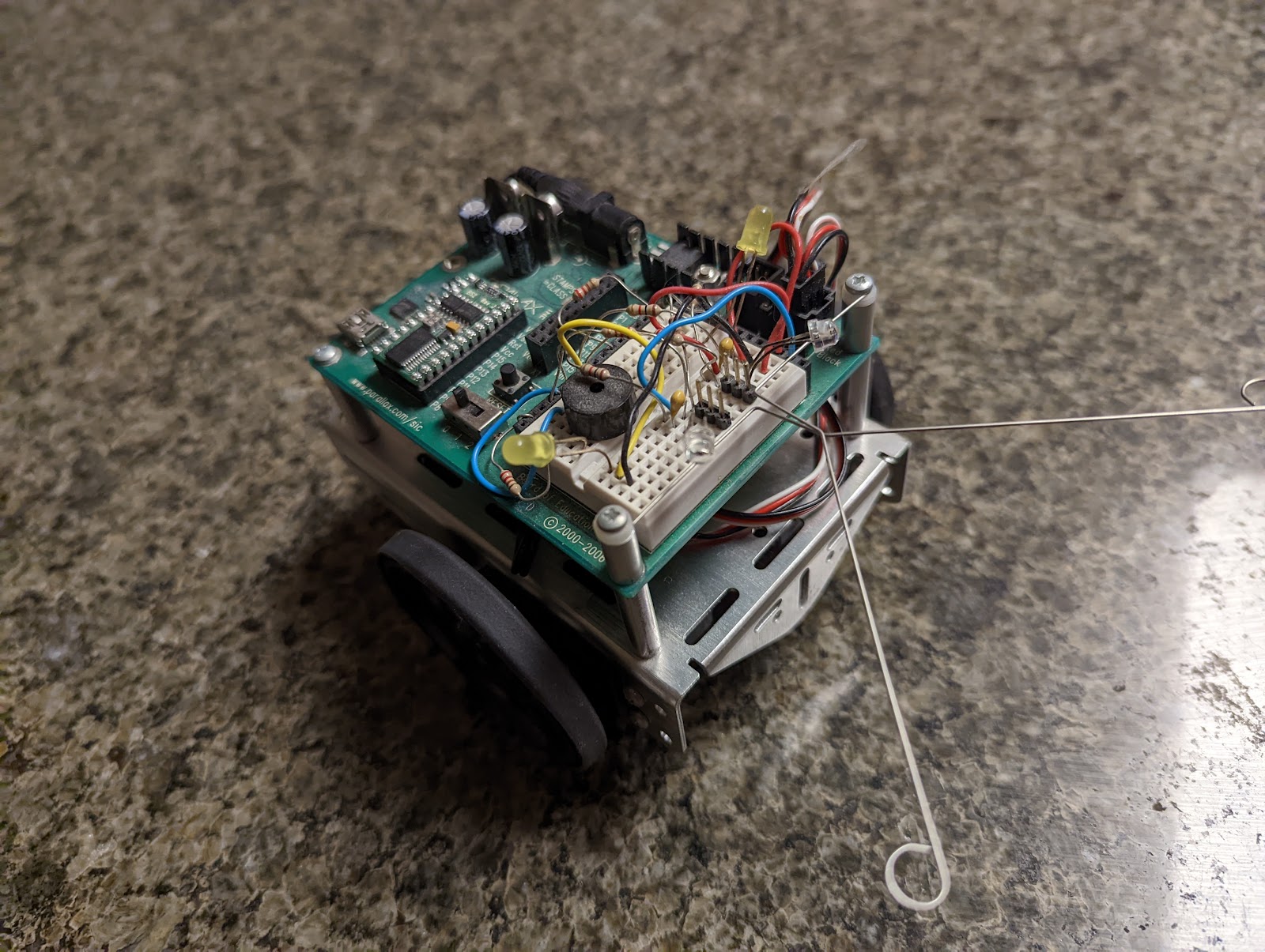
After I worked with the LEGO Mindstorms kit (see my post here), I moved on to BOE-Bot, an educational robotics kit that teaches basic electric circuits and robot control. I picked up my kit at the Boy Scouts store (back when I was actively in Boy Scouts of America) as part of the robotics merit badge. When I built it, I found the accompanying book very helpful when learning PBASIC (the textual programming language used).
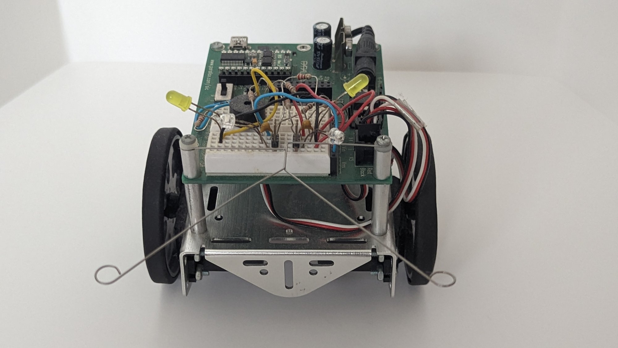
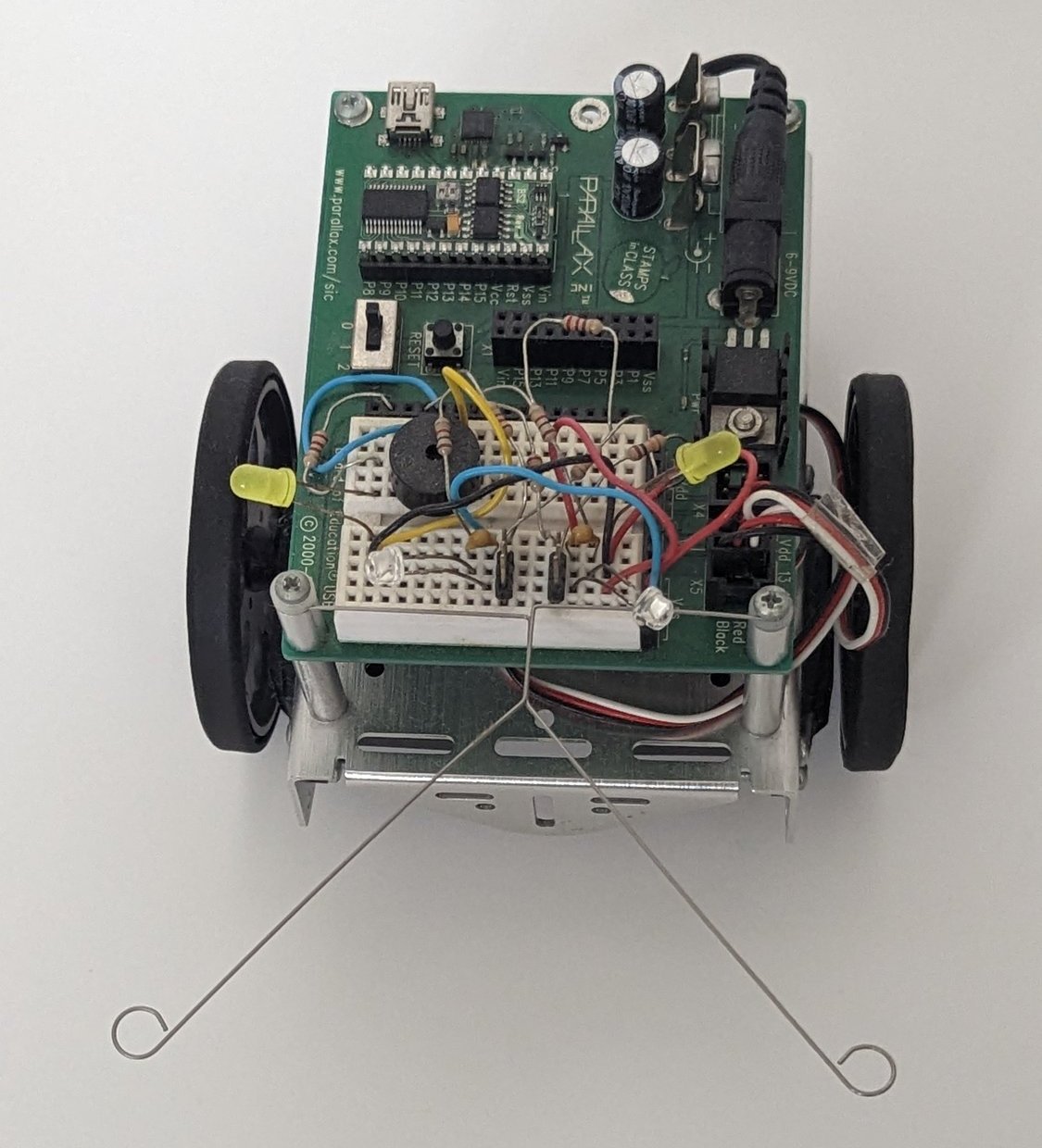
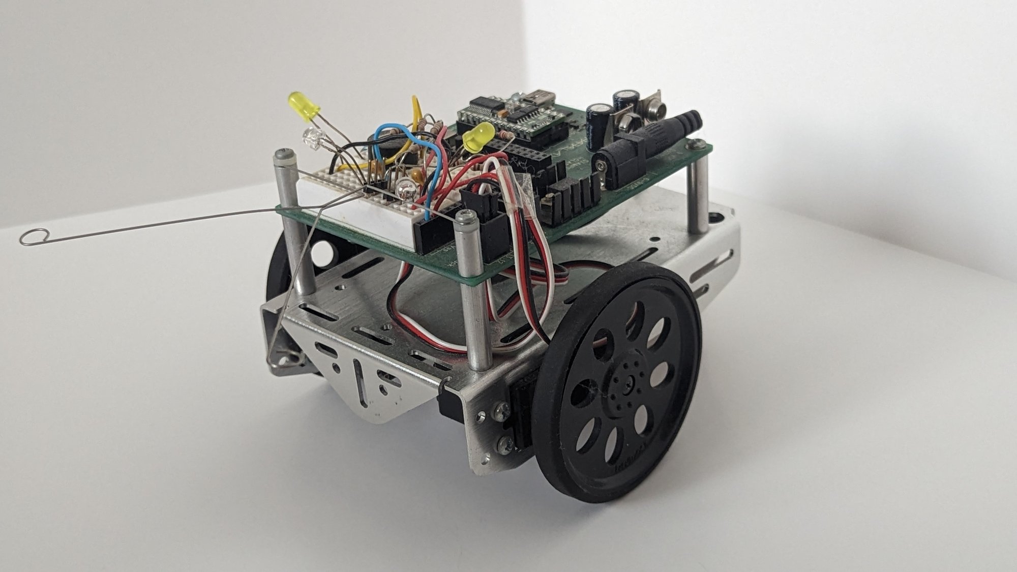
My BOE-Bot with phototransistor eyes and collision whiskers.
The core of BOE-Bot is the BASIC Stamp microcontroller. It’s a small DIP IC/PCB with an (old) PIC microcontroller and EEPROM that is programmed using PBASIC (Parallax BASIC). This microcontroller hooks up to the Board of Education (BOE) that provides breakout of the GPIO, power regulation, and a small breadboard for various simple circuits. It also provides a handy breakout for servo motors.
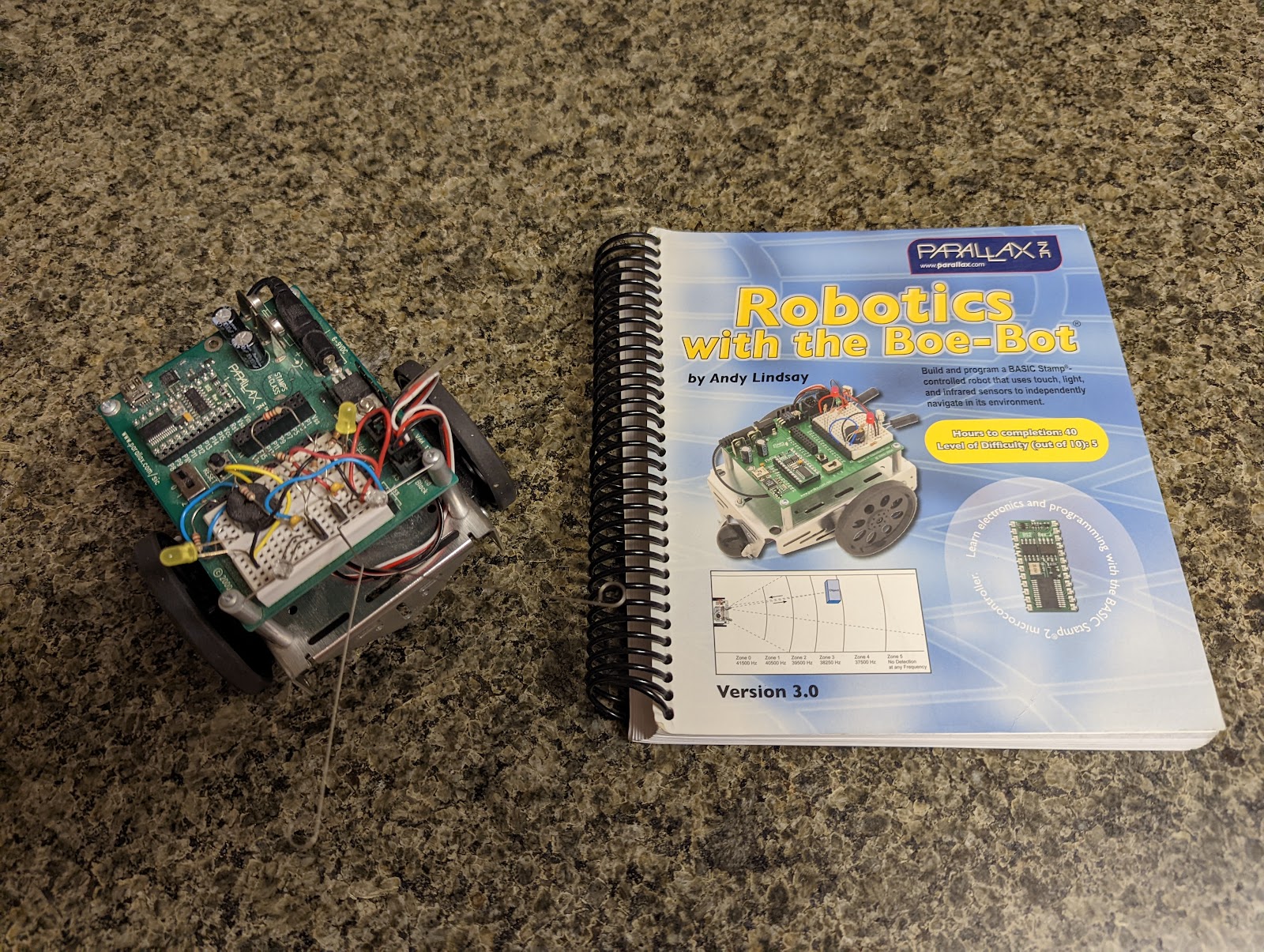
BOE-Bot with the official textbook.
The robot kit itself is well built, with a polished aluminum chassis to house two servo motors and the BOE. The wheels themselves are less great. While the plastic is sturdy (it has survived several years of use), you have to cover them with a rubber band that is tricky to get on. Plus this rubber band degrades over time. I did buy a large set from DigiKey on a recent repair of this robot. This seems to be fixed in new versions of the kit but alas I did not get that version back in the day.
Onto the circuit. I followed the accompanying book, Robotics with the Boe-Bot by Andy Lindsay, to build several rudimentary circuits along with the code to interact with them. Each of these circuits teaches fundamental concepts in embedded systems and I was glad that the book eased me into each one. I will detail each below.
The Circuit
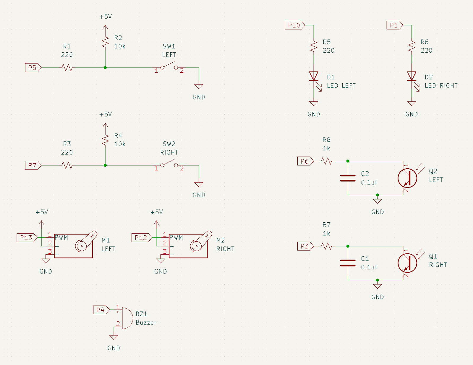
Schematic capture of the circuits built for BOE-Bot. Not shown is the microcontroller itself; pins noted (P1, P3, P4, P5, P6, P7, P10) are the pins on the Board of Education breakout. Servo motors are broken out in a separate connector (P12, P13).
Whisker Switches: Driving forward is all well and good until you crash into something at which point, if your robot can’t detect that it has stopped moving, it will helplessly continue attempting to drive forward. These whiskers offer a simple electro-mechanical sense of collision. The collision circuits connect digital input pins (P5 for left whisker and P7 for right whisker) to a current limiting resistor and a pullup resistor. Normally, the whisker switch is open (not in collision) so the pullup resistor connected to +5V pulls the rest of the circuit and the digital input pin up to +5V. This works because of Ohm’s law: V = IR. Assuming the digital input doesn’t draw any current then there is no voltage drop over the 10k resistor.
However, when the switch is pressed the digital input line short-circuits to ground (0V). So why doesn’t our circuit blow up? Because we properly chose a pullup resistor with a high enough resistance such that a 5V drop across it only passes 0.5 mA and dissipates 2.5mW (P = VI).
What about the other resistor in series with the digital input? Well this is mostly for our protection. As a general rule, microcontrollers can only source or sink so much current. So putting this resistor in helps us if we accidentally program this pin to be an output. We would be fine if we set the output to low since it would just sink (that means pull in) current from +5V through a large resistor. But if we didn’t have the in-series 220 Ω resistor and we set the pin to be high (at +5V) then we would be in serious trouble. In this scenario our microcontroller is being asked to supply as much current as possible, which will certainly cause it to break. But with the resistor we only will source (push out) 25ish mA, high but reasonable.
LEDs: Another staple circuit is the humble LED. On BOE-Bot we are using these to indicate turning direction (explained more in the programming section). The circuit itself is a digital output pin connected to a current limiting resistor to a diode to ground. In this configuration we are sourcing current from the microcontroller (about 15 mA assuming a standard voltage drop over the diode). In this configuration we can set the pin to HIGH (one or +5V) to turn the LED on and LOW to turn the LED off.
We could have also sunk current from an LED connected to +5V but then our LED is active LOW (pin is grounded) when the LED is on, which is frankly just a bit harder to think about. One would want to do this if we expected a higher current load as there is this general rule that it’s easier for electronics to sink current than to source it.
Continuous Rotation Servos: BOE-Bot is a mobile robot that uses two continuous rotation servos for its differential drivetrain. A servo motor is simply a motor with some kind of internal feedback / control loop. Normally a servo motor is used to move to a particular position (think motors for a robot arm). The ones on BOE are continuous, meaning they spin freely, so we give a target speed instead of a position.
Commanding a servo motor requires a digital output pin to produce a PWM (pulse width modulation) waveform. The PWM waveform has parameters of duty-cycle and frequency. Frequency tells us how quickly we cycle our digital output pin from HIGH to LOW and back to HIGH. Duty-cycle tells us how long we should stay HIGH (or LOW) within a single period of the waveform.
Back to servos, the trick is that the servo doesn’t actually care about the duty cycle percentage; it watches the width of each HIGH pulse. Send a 1.5 ms pulse every 20 ms or so and a continuous rotation servo holds still. Stretch the pulse to 1.7 ms and it spins full speed counterclockwise. Shrink it to 1.3 ms and it spins full speed clockwise. Everything in between maps to a speed in between. This is exactly what the code does later on: PULSOUT counts time in 2 microsecond units, so the 650 and 850 constants you will see are the 1.3 ms and 1.7 ms pulses, and in-between values like 720 and 780 are the gentler turns.
Notice that the frequency isn’t doing the signaling here. Servos are forgiving about how often the pulses arrive; as long as they show up every 20ish milliseconds the motor itself will be more than happy to interpret the pulse width as a speed.
* Lastly, if we were talking about positional servos all of the above would be true except instead of speed we would map angular position to pulse width.
Phototransistors: The eyes are the windows to the soul… err world. In our case, BOE-Bot’s eyes are two phototransistors pointed left and right. The circuit used has a clever charge-and-decay trick to determine an analog (not just binary) light level. Our goal is to use this to steer BOE-Bot toward the light as a photovore.
Microcontrollers are inherently digital, binary devices. They think in ones and zeros. But our world is not just on or off, it’s every step in between and the kitchen sink. Light itself has a degree of brightness even if your light source is either on or off. If we want our robot to see this we need some way of converting the analog value of brightness into a number (as a formatted set of ones and zeros). Fancy microcontrollers have built-in ADCs that can be directly hooked up and with a bit of programming will spit out a number. Our BASIC Stamp ain’t as fancy but it can do something similar (it’s kind of how an ADC works under the hood) by charging up a circuit and then waiting for it to naturally drop back to zero volts.
In our circuit we use a capacitor and the transistor as a sort of light adjustable RC circuit. RC circuit just means resistor capacitor circuit. The process starts by setting our pin to output HIGH (+5V) voltage, charging up the capacitor, and then switching our pin to input. We now read back HIGH. So we wait a bit and check again; still HIGH. And again until it reads LOW. During that time we count each check we did. The more checks, the longer it took to decay to LOW and thus it has a higher resistance.
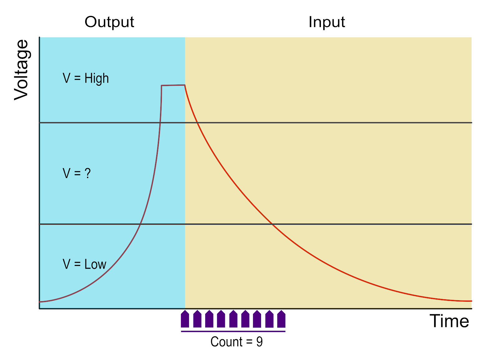
Graph of RC charge-decay process. X axis is time. Y axis is Voltage. The process starts with pin outputting a high voltage to charge up the capacitor. Then pin changes to input. Capacitor voltage decays due to phototransistor leaking current. During this time, the microcontroller checks for the voltage to go back to a low state; finding nine checks were needed.
The electrical theory is a bit more complex but generally speaking the phototransistor only allows so much current to flow out of the capacitor. A phototransistor itself has a “resistance” affected by the ambient light level. In a bright, sun-filled room the effective resistance is very low (phototransistor is ON) but in a dark room with the light off, the resistance is near infinity (phototransistor is OFF). Between those two states is some mapping of current flow to brightness.
Once we check both RC circuits in the code, we can compare the light levels on the left and right side of BOE-Bot. Then similar to an op-amp BEAM photovore we can steer toward the light.
Piezo Buzzer: A buzzer provides an audible tone, useful for indicating the state of the robot. The circuit is merely a digital output connected to the piezo buzzer. When we apply a square wave at a certain range of frequencies the buzzer vibrates producing an audible sound. Similar to the servo motor we are wiggling a digital output with careful timing, except now the frequency is what carries the signal (mapping to audible tone) instead of the pulse width.
The Program
My code can be found on GitHub under Simple-Hobby-Robot-Projects/BOE-Bot. Note that the repository is archived and the code hasn’t been maintained. And while I am going to discuss the spaghetti code here, I don’t really plan on improving it. The purpose of this post is to reflect back on the code I wrote; documenting some useful / teachable aspects.
First keep in mind the following convention for left and right of BOE-Bot.
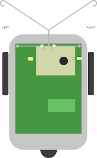
We will refer to left and right of BOE-Bot as shown.
Let’s look at the first snippet, which handles memory allocation and initialization.
'Hardware defined constants
LIGHT_SENSE_LEFT      CON   6
LIGHT_SENSE_RIGHT     CON   3
BUZZER                CON   4
TOUCH_SENSE_LEFT      VAR   IN5
TOUCH_SENSE_RIGHT     VAR   IN7
LED_LEFT              CON   10
LED_RIGHT             CON   1
MOTOR_LEFT            CON   12
MOTOR_RIGHT           CON   13

'Memory Allocation
pulseCount            VAR   Byte
cornerCounter         VAR   Byte
cornerCounter = 0
lightLvlLeft          VAR   Word
lightLvlRight         VAR   Word
i                     VAR   Byte
Snippet two, main loop.
main:
  'Initial startup frequency to notify that the program has indeed started
  FREQOUT BUZZER, 2000, 3000

  'run the robot program forever!
  DO
  'turn off LEDs
  LOW LED_LEFT
  LOW LED_RIGHT

  'IF touch sensors are not pressed then follow the light
  IF TOUCH_SENSE_RIGHT = 1 AND TOUCH_SENSE_LEFT = 1 THEN

    'read the light values from sensors
    HIGH LIGHT_SENSE_LEFT
    PAUSE 1
    RCTIME LIGHT_SENSE_LEFT, 1, lightLvlLeft
    HIGH LIGHT_SENSE_RIGHT
    PAUSE 1
    RCTIME LIGHT_SENSE_RIGHT, 1, lightLvlRight

    'If the light level low then ignore the light sensor behavior AND just run a
    'wall banger script for a bit
    IF (lightLvlLeft < 100 AND lightLvlRight < 100)THEN
       GOSUB wallBangerLoop 'will kick out of loop after some time period
    'If the light level too high then ignore the light sensor behavior
    'AND just run a wall banger script for a bit
    ELSEIF(lightLvlLeft > 20000 AND lightLvlRight > 20000) THEN
      GOSUB wallBangerLoop 'will kick out of loop after some time period
    'If the left has less light than right side then turn right
    ELSEIF lightLvlLeft < lightLvlRight THEN
      GOSUB rightPulseSoft
    'If the right has less light than left side then turn left
    ELSEIF lightLvlLeft > lightLvlRight THEN
      GOSUB leftPulseSoft
    'If they are equal value then go straight
    ELSE
      GOSUB forwardPulse
   ENDIF

  'touch sensors are pressed determine which one it is and take evasive action
  ELSE
    GOSUB takeEvasiveAction
  ENDIF
LOOP
The main loop consists of two primary behaviors: light-seeking and obstacle avoidance. If no touch sensors are activated, the robot will follow the light-seeking routine. If a touch sensor is activated, the robot will take evasive action via the takeEvasiveAction routine. There is also a way to short-circuit the light-seeking routine if the light sensors are producing data at the extremes (too bright or too dark of an environment); this is handled by the wallBangerLoop routine.
The light-seeking routine itself is pretty straightforward.
- If the left sensor is brighter than the right sensor then turn left
- If the right sensor is brighter than the left sensor then turn right
- Else keep going straight
My code doesn’t match that list, and I only figured out why it worked while writing this post. RCTIME returns smaller values in brighter light, so the branch commented as the left side having less light actually fires when the left side is brighter. The motor constants are backwards too: my own schematic wires the left servo to P13, yet the code declares MOTOR_LEFT as 12, which means rightPulseSoft physically veers the robot left. The two bugs cancel out, so the robot still chases the light. I recall tearing my hair out over exactly this sort of thing when I was first learning to code on this bot. Both bugs are still in the code.
Snippet three, obstacle avoidance behavior.
takeEvasiveAction:
  'IF the touch sensors are not both active then increment
  'a counter since BOE-bot may be in a corner, if enough times
  'in this then BOE-bot will backup and spin 180
  IF (TOUCH_SENSE_RIGHT <> TOUCH_SENSE_LEFT)THEN
    cornerCounter = cornerCounter + 1
    'In a corner so backup and leave corner
    IF (cornerCounter > 4) THEN
      cornerCounter = 0
      HIGH LED_LEFT
      HIGH LED_RIGHT
      GOSUB backup
      LOW LED_LEFT
      LOW LED_RIGHT
      GOSUB turnLeft
      HIGH LED_LEFT
      HIGH LED_RIGHT
      GOSUB turnLeft
    ENDIF
  ENDIF

  'IF both sensors pressed then turn 180 degrees
  IF (TOUCH_SENSE_LEFT = 0) AND (TOUCH_SENSE_RIGHT = 0) THEN
    HIGH LED_LEFT
    HIGH LED_RIGHT
    GOSUB backup
    GOSUB turnLeft
    GOSUB turnLeft
  'If left sensor is pressed the turn right
  ELSEIF (TOUCH_SENSE_LEFT = 0) THEN
    HIGH LED_LEFT
    GOSUB backup
    GOSUB turnRight
  'If right sensor is pressed then turn left
  ELSEIF (TOUCH_SENSE_RIGHT = 0) THEN
    HIGH LED_RIGHT
    GOSUB backup
    GOSUB turnLeft
  ENDIF
  RETURN
This snippet contains the takeEvasiveAction subroutine. It reads the touch sensors to decide how to get BOE-Bot unstuck.
The logic is somewhat straightforward:
- If one sensor is activated while the other is not, a counter increments. After a few occurrences, the bot backs up and performs a 180° turn. Presumably if we keep oscillating (and thus incrementing the counter) we are stuck in a corner or other weird situation. Retreating back to known navigable space is better than bouncing back and forth.
- When both sensors are triggered, BOE-Bot immediately reverses and turns 180°. We have probably collided with a wall head-on.
- A single sensor trigger results in a backup and a turn in the opposite direction of the activated sensor.
The LEDs show which maneuver is running.
Snippet four, wall banger routine.
wallBangerLoop:
  FOR i = 0 TO 100
    IF TOUCH_SENSE_RIGHT = 1 AND TOUCH_SENSE_LEFT = 1 THEN
      GOSUB forwardPulse
    ELSE
      GOSUB takeEvasiveAction
    ENDIF
  NEXT
  RETURN
This snippet simply blocks within a loop for 100 cycles and either moves forward if neither touch sensor is pressed or takes evasive action (as described above).
Nomenclature: Wall-banger is a common term used to describe a robot that is driving around (perhaps with a goal like mapping or just existing) and detects walls, rotates, drives, detects wall, etc.
Snippet five, movement subroutines.
turnLeft:
  FOR pulseCount = 0 TO 20
    GOSUB leftPulseHard
  NEXT
  RETURN

turnRight:
  FOR pulseCount = 0 TO 20
    GOSUB rightPulseHard
  NEXT
  RETURN

backup:
  FOR pulseCount = 0 TO 40
    GOSUB backupPulse
  NEXT
  RETURN

forwardPulse:
  PULSOUT MOTOR_RIGHT, 850
  PULSOUT MOTOR_LEFT, 650 ' used to be 850 but is set for correction
  PAUSE 20
  RETURN

leftPulseHard:
  PULSOUT MOTOR_RIGHT, 650
  PULSOUT MOTOR_LEFT, 650
  PAUSE 20
  RETURN

leftPulseSoft:
  PULSOUT MOTOR_RIGHT, 850
  PULSOUT MOTOR_LEFT, 720
  PAUSE 20
  RETURN

rightPulseHard:
  PULSOUT MOTOR_RIGHT, 850
  PULSOUT MOTOR_LEFT, 850
  PAUSE 20
  RETURN

rightPulseSoft:
  PULSOUT MOTOR_RIGHT, 780
  PULSOUT MOTOR_LEFT, 650
  PAUSE 20
  RETURN

backupPulse:
  PULSOUT MOTOR_RIGHT, 650
  PULSOUT MOTOR_LEFT, 850
  PAUSE 20
  RETURN
These subroutines control BOE-Bot’s low-level movements, such as turning left, right, backing up, and moving forward. Each subroutine sends appropriate control signals to hardware for a calibrated duration.
The BOE-Bot Today
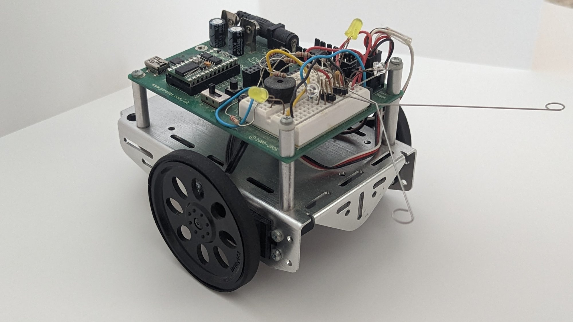
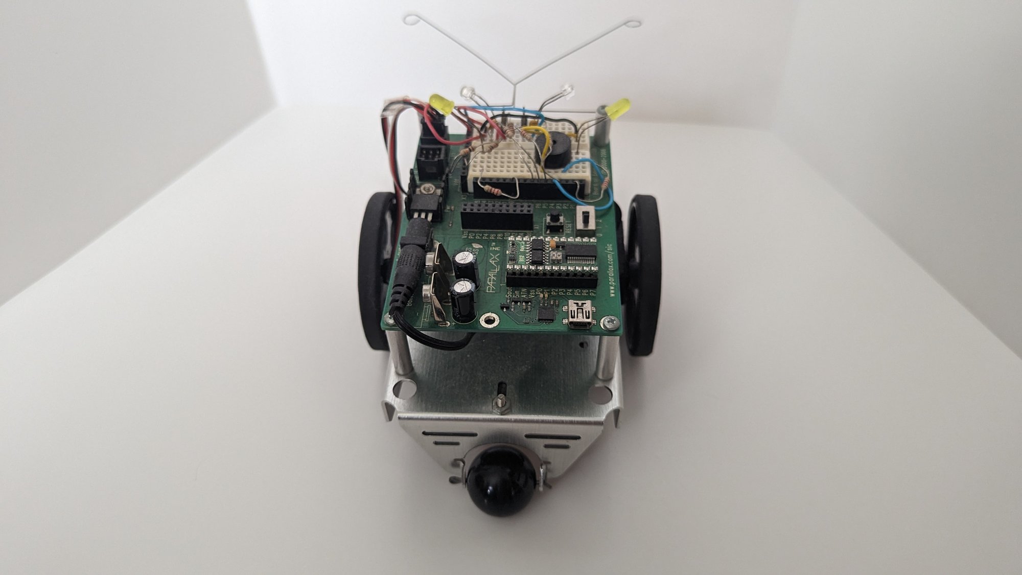
Closing Thoughts
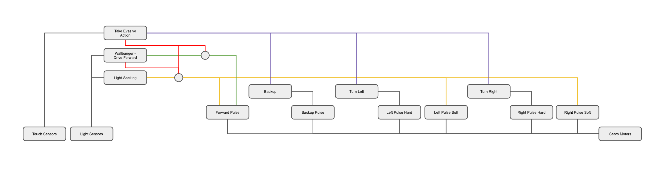
I want to wrap everything up in a neat little bow by documenting the subsumption architecture controlling BOE-Bot.
Nomenclature: Subsumption Architecture is a behavior-based approach that organizes a robot’s behavior into layers, with each layer responsible for a specific task. Higher layers can subsume (or suppress) the output of lower layers to control the overall behavior of a robot.
Below is the subsumption architecture diagram starting on the left-bottom with sensors, moving through the subsumable control layers, and on the right are lower-level motor control primitives. Notably, the light-seeking behavior we discussed earlier is subsumable by the wall banger routine if the light level is out of bounds. Both wall banger and light-seeking are subsumable by the evasive action behavior triggered when the touch sensors detect collision.
In my journey through robotics back in high school, I muddled the implementation details of programming, circuits, and mechanics with the theoretical control structures. But I think this is okay. A novice doesn’t need to grasp the architecture when they are first tinkering. Doing is better than not.
But it is also good to reflect on what was built and what could have been improved (even if the improvement will never actually be implemented). Generating and understanding the architecture diagram (even if it’s after the fact) is probably the most impactful part of this exercise.
If you have feedback, send it my way on X. Keep building.