ESP8266 Hacked KOIOS Air Filter using Okos Polip Device-to-Cloud Service
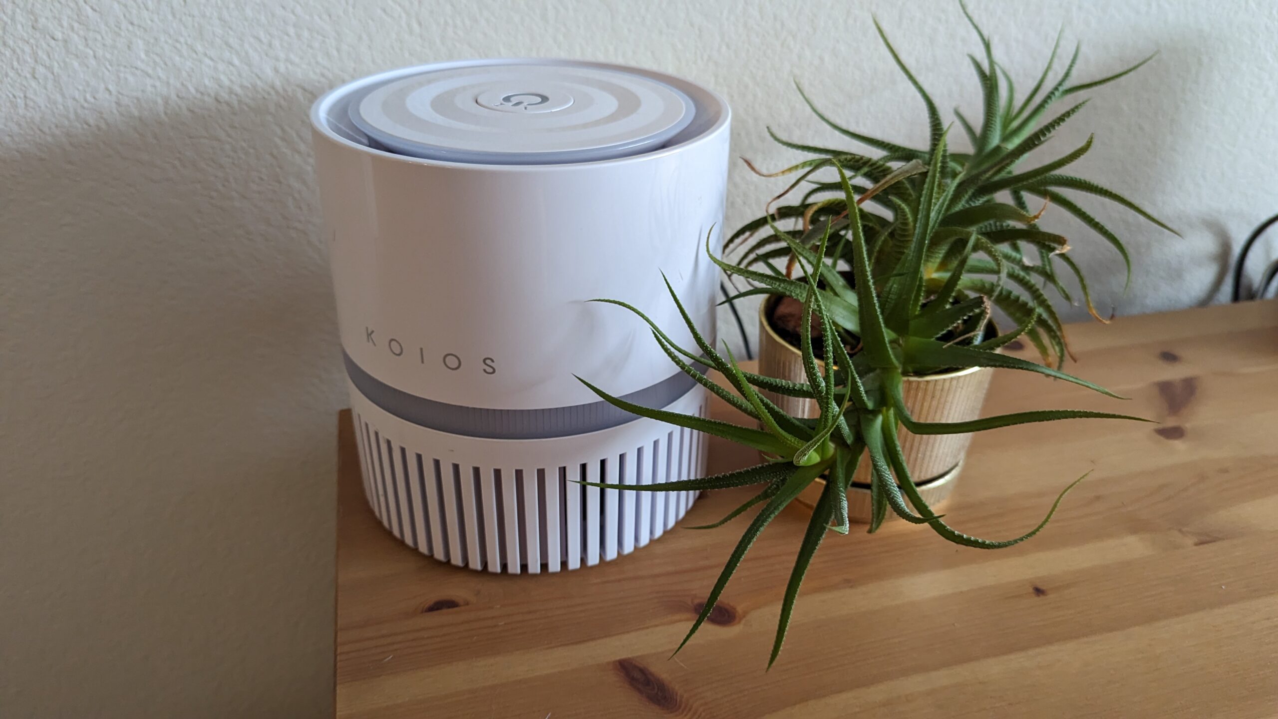
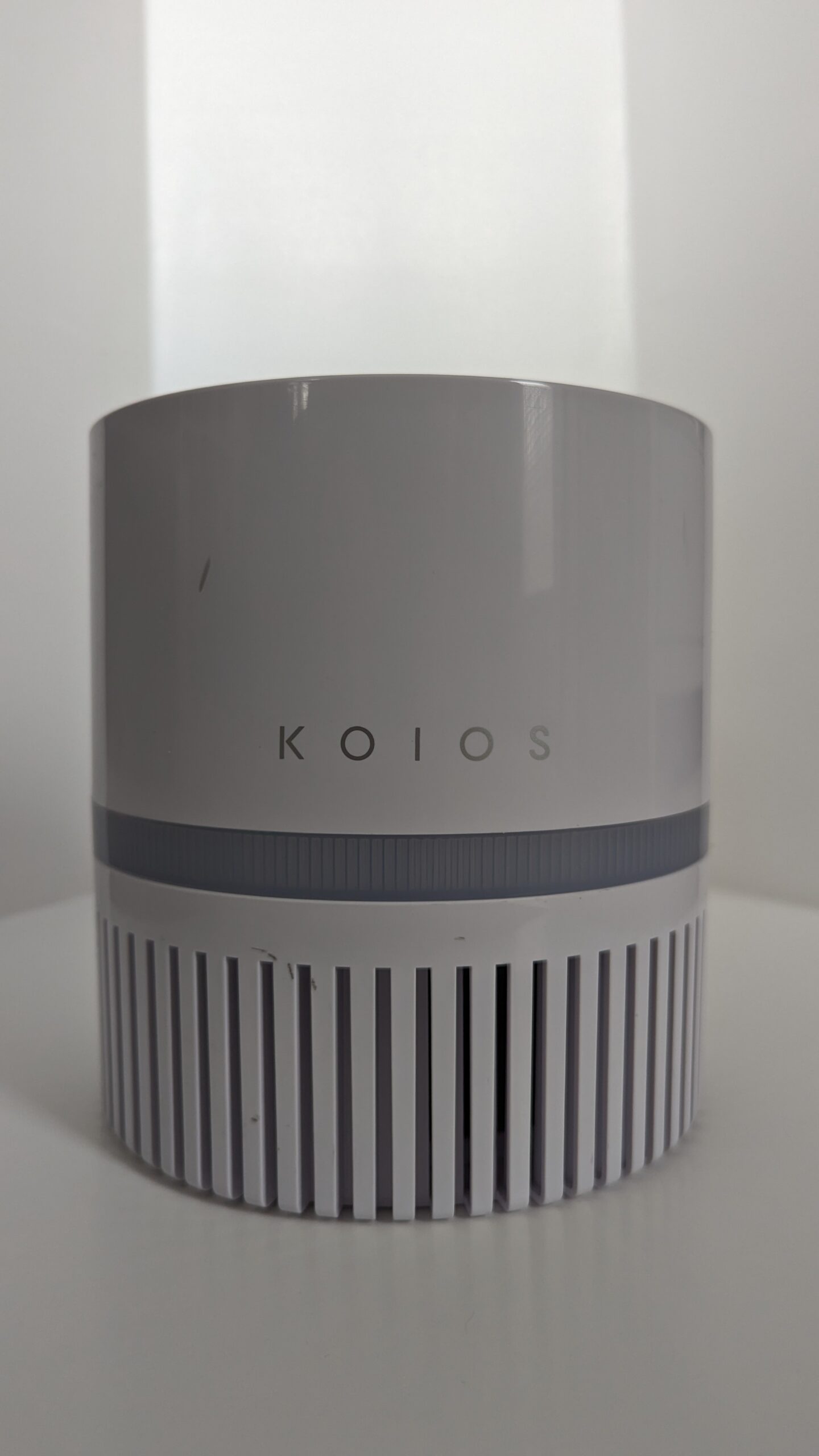
When I moved out to the Bay Area (California), I purchased a small KOIOS air filter to keep the wildfire smoke at a reasonable level in my (at the time) one-bedroom apartment. After a while, I upgraded to a larger air filter making this one redundant.
So given it wasn’t Wi-Fi enabled and I had the urge to build a better home automation setup, I got started hacking. Turns out this little unit was pretty easy to control with an ESP8266.
Below I will go through the hardware hack and then the two firmware / software approaches to control the air filter.
Hardware
Basic KOIOS air filter is configured as follows:
- 12V DC power supplied into the unit via barrel jack
- Internally one fan (with filter)
- User input is a single button. Button controls state
- Off
- On High
- On Low
- Holding button goes into “dark” mode with last state active
- LEDs within button indicates state
- LEDs in a ring on base to indicate running
Teardown
-
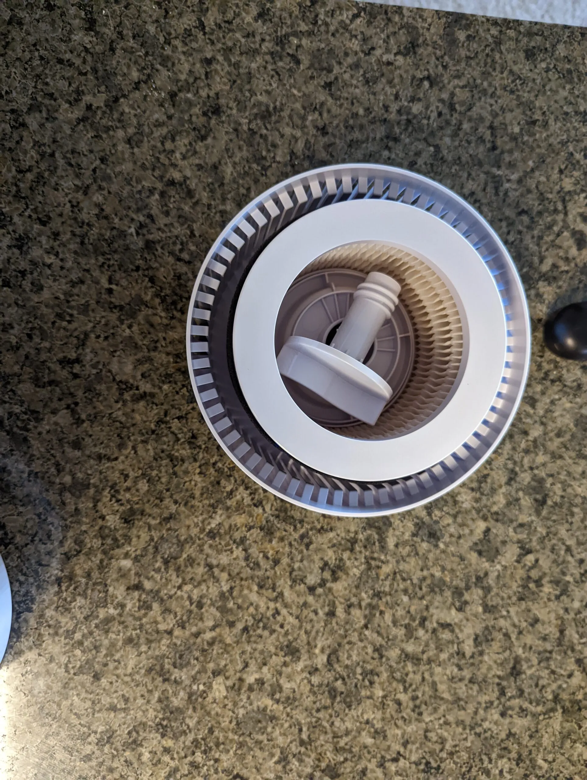
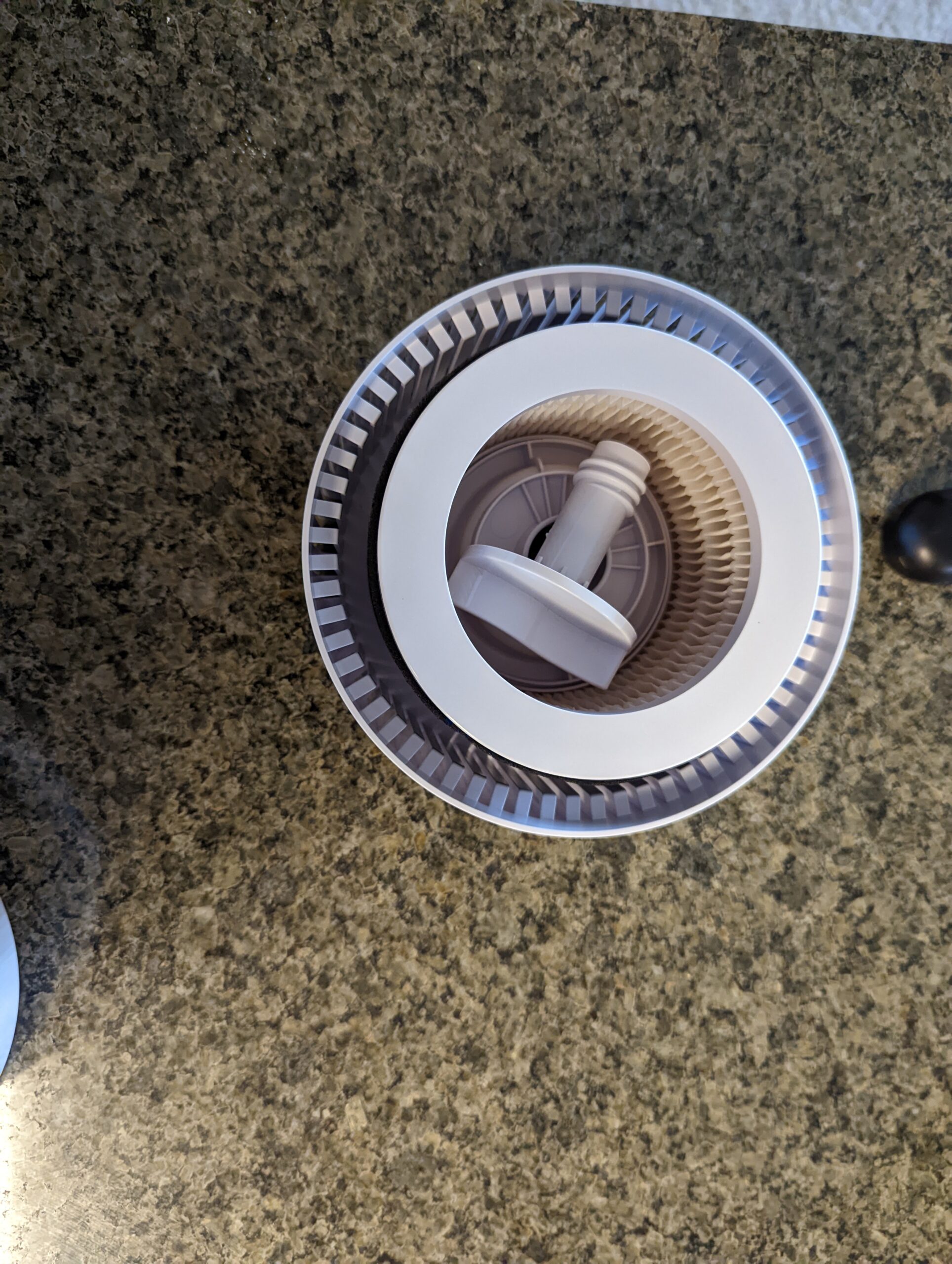
Unplug unit and remove filter from base. There is a large plastic “screw” that holds everything together.
-
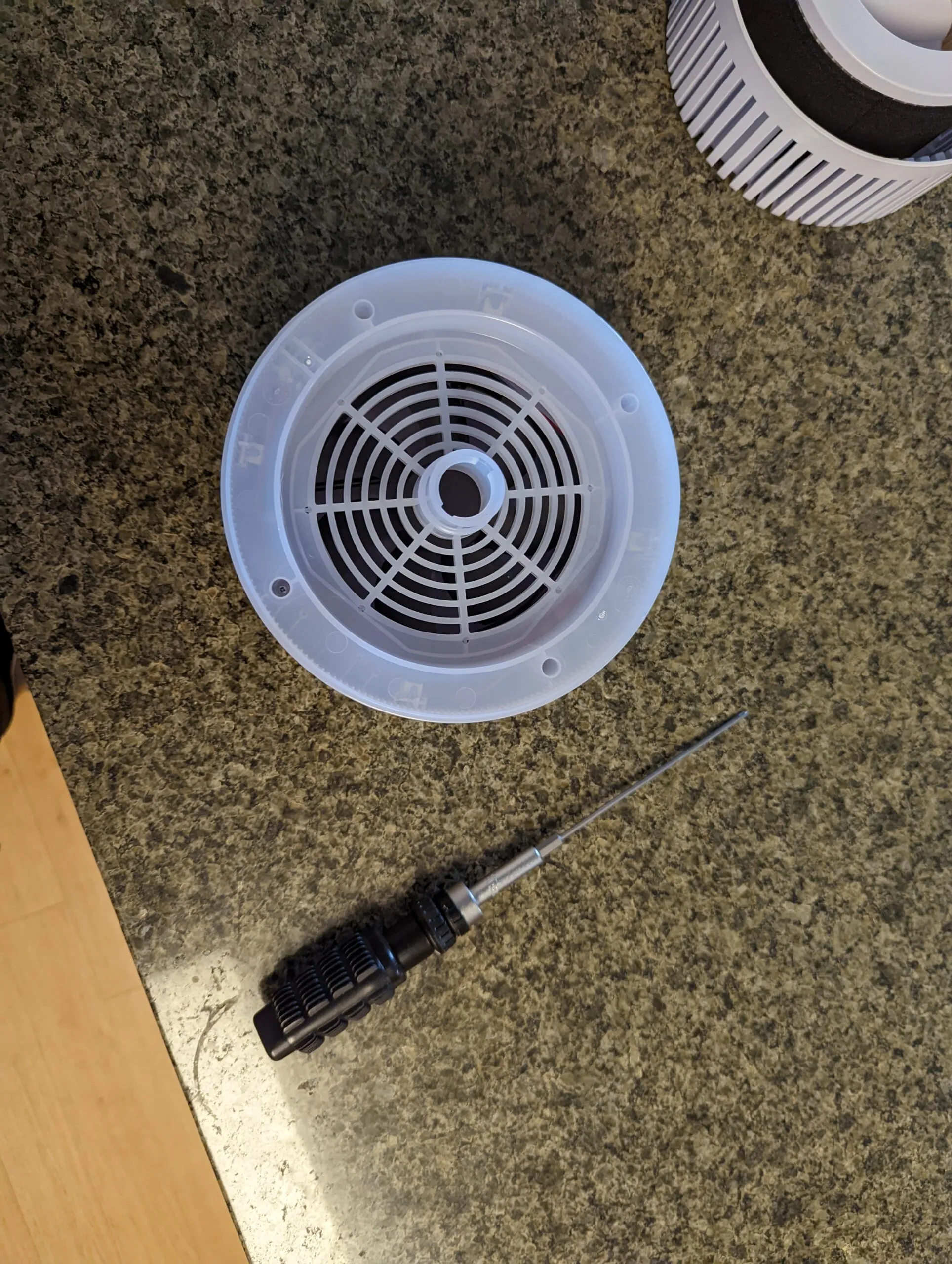
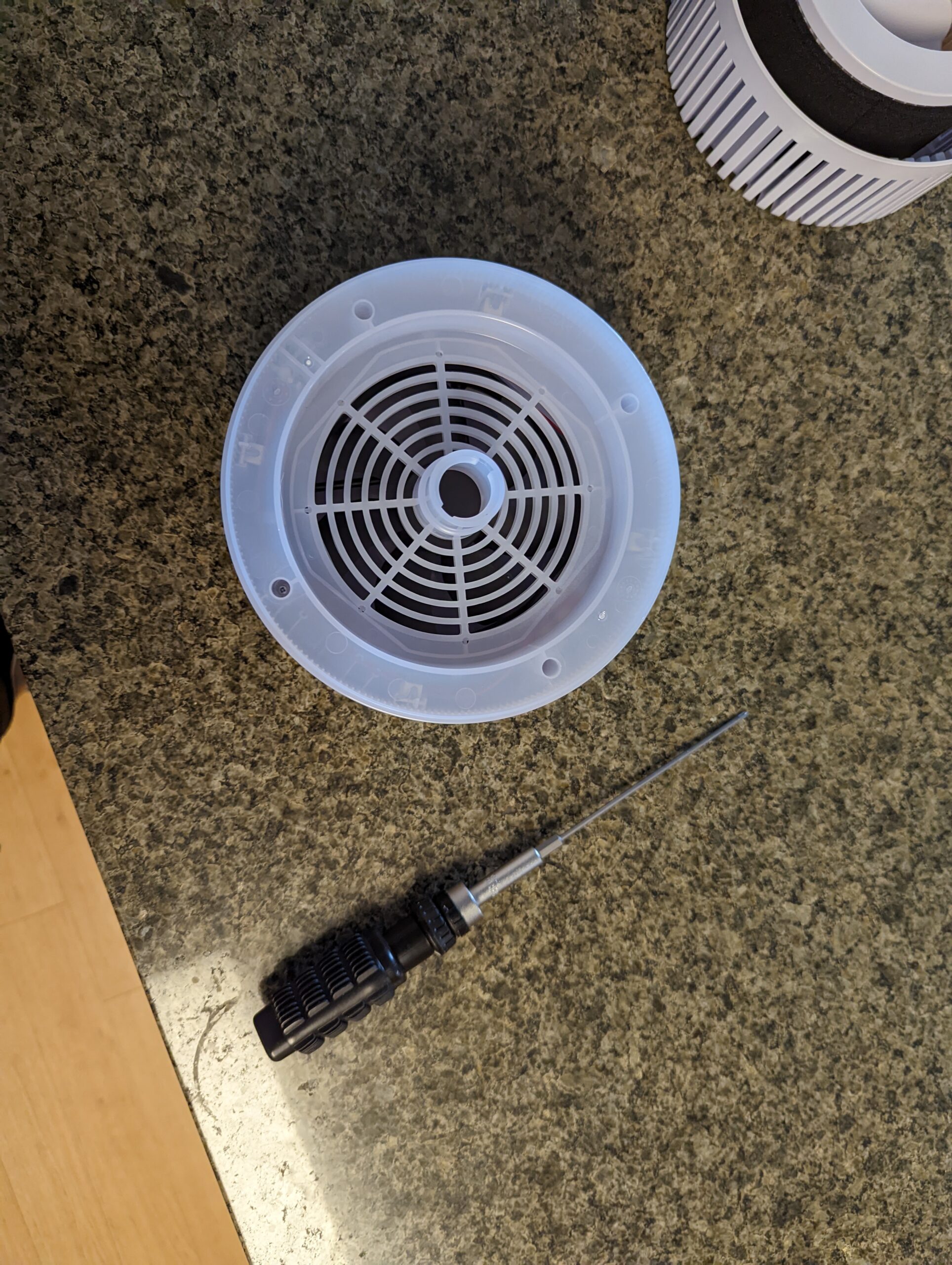
Next we need to take off the bottom of the top-half. This is held together by 4 screws that are inset pretty deep. Had to buy really long Phillips head screwdriver bits to get them out.
-
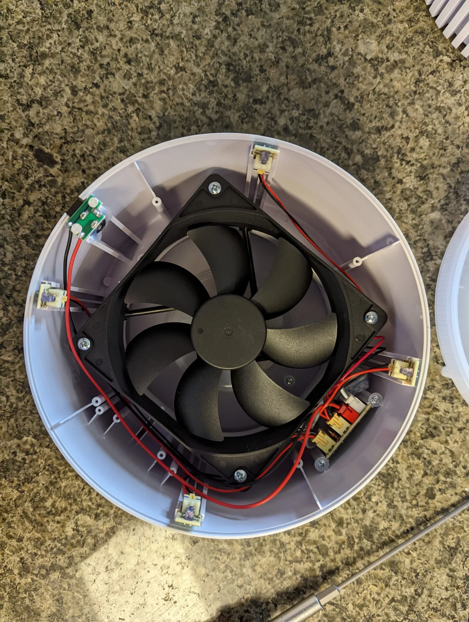
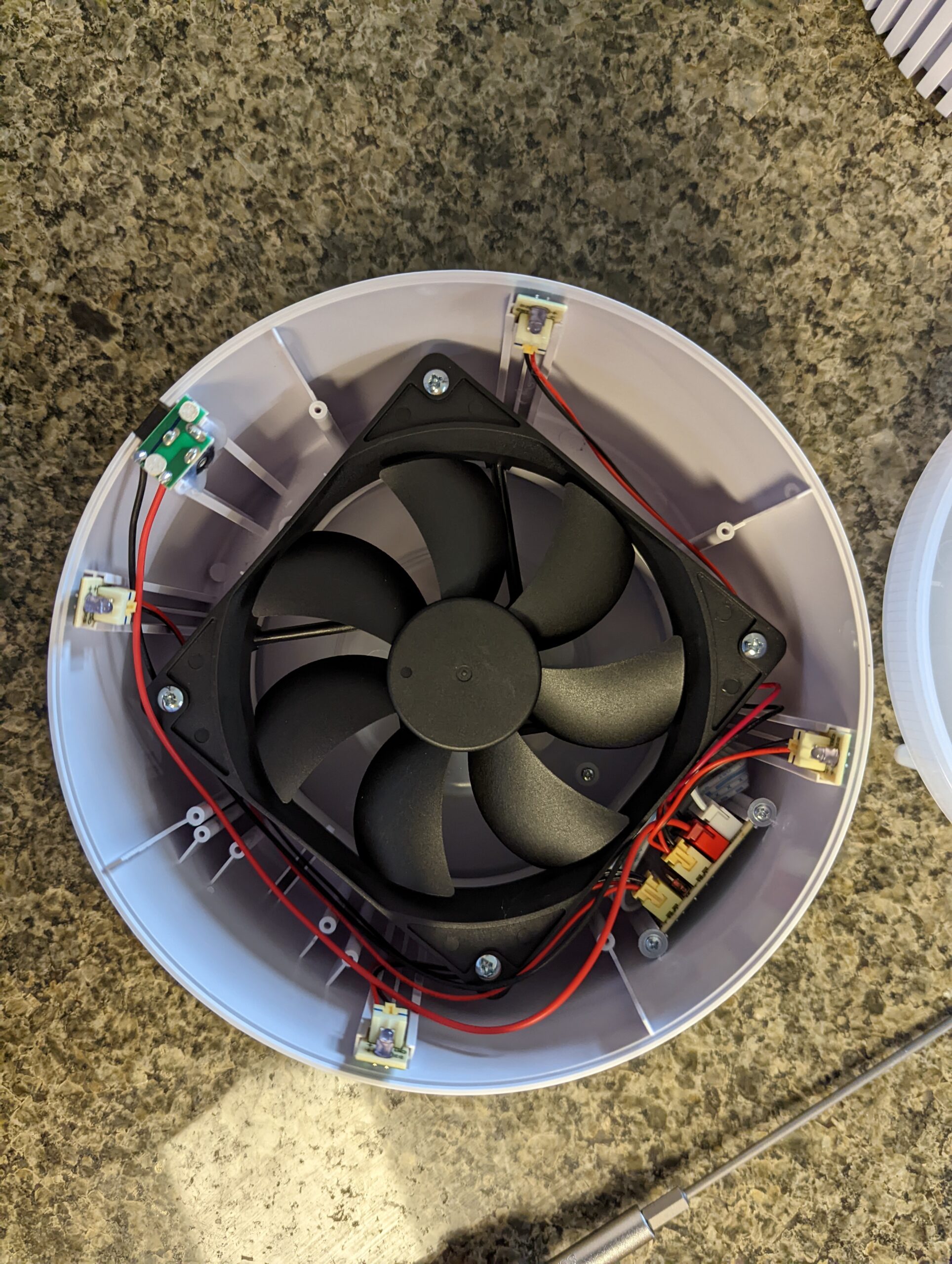
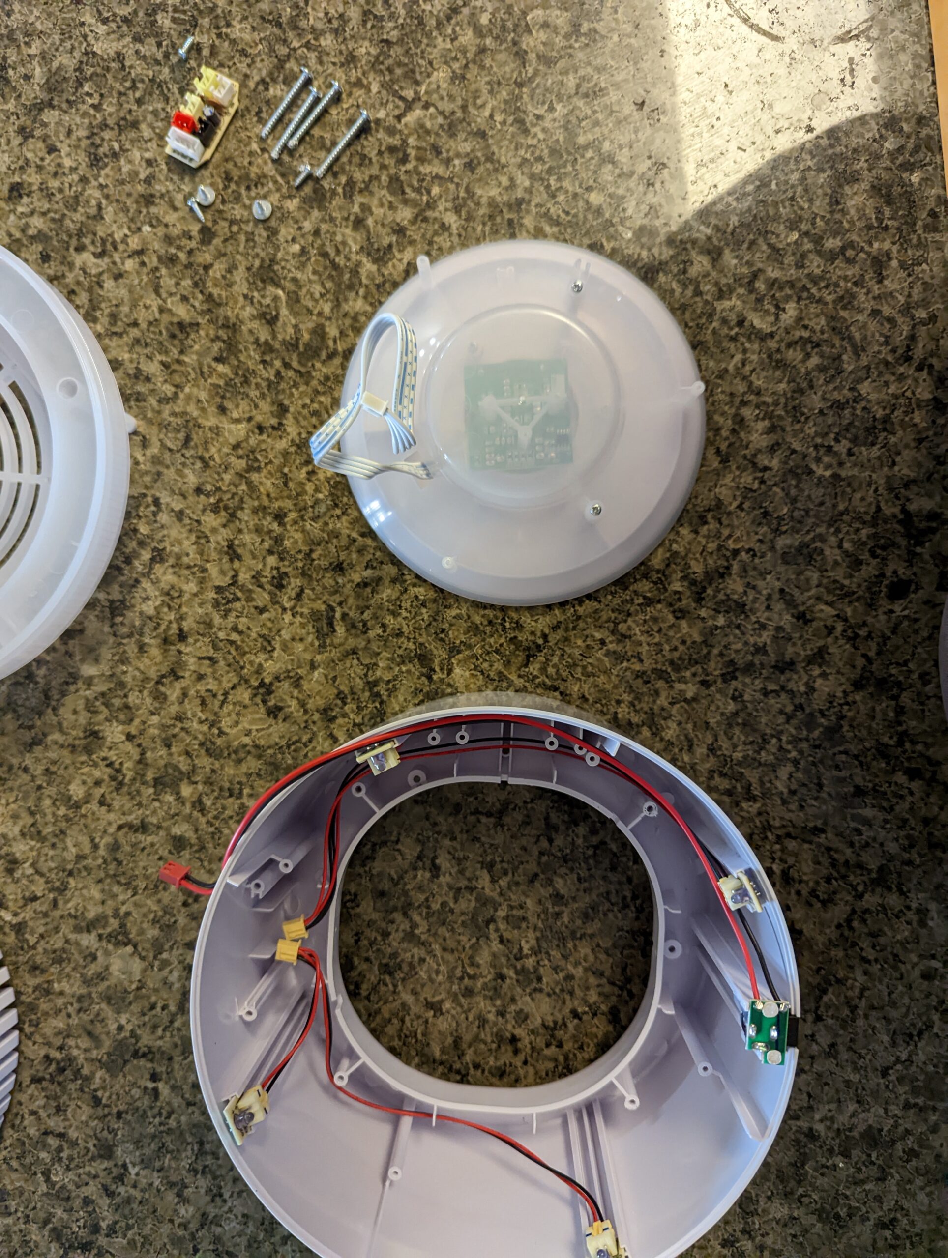
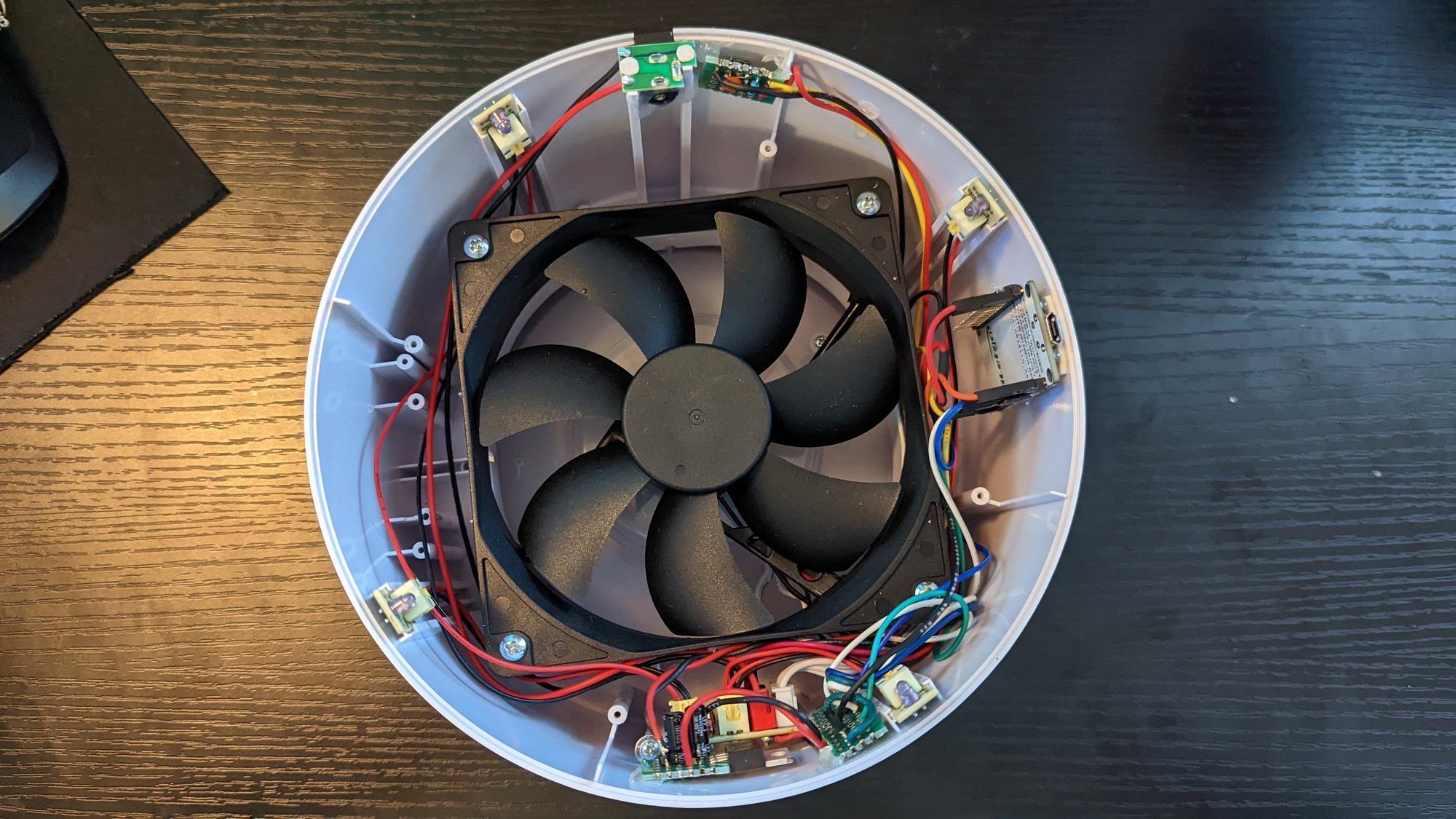
Now we have access to the electronics. Looks like they use a standard fan, as you would find in a PC build. Interesting… The little boards around the rim are the LEDs for the light ring in the base.
-
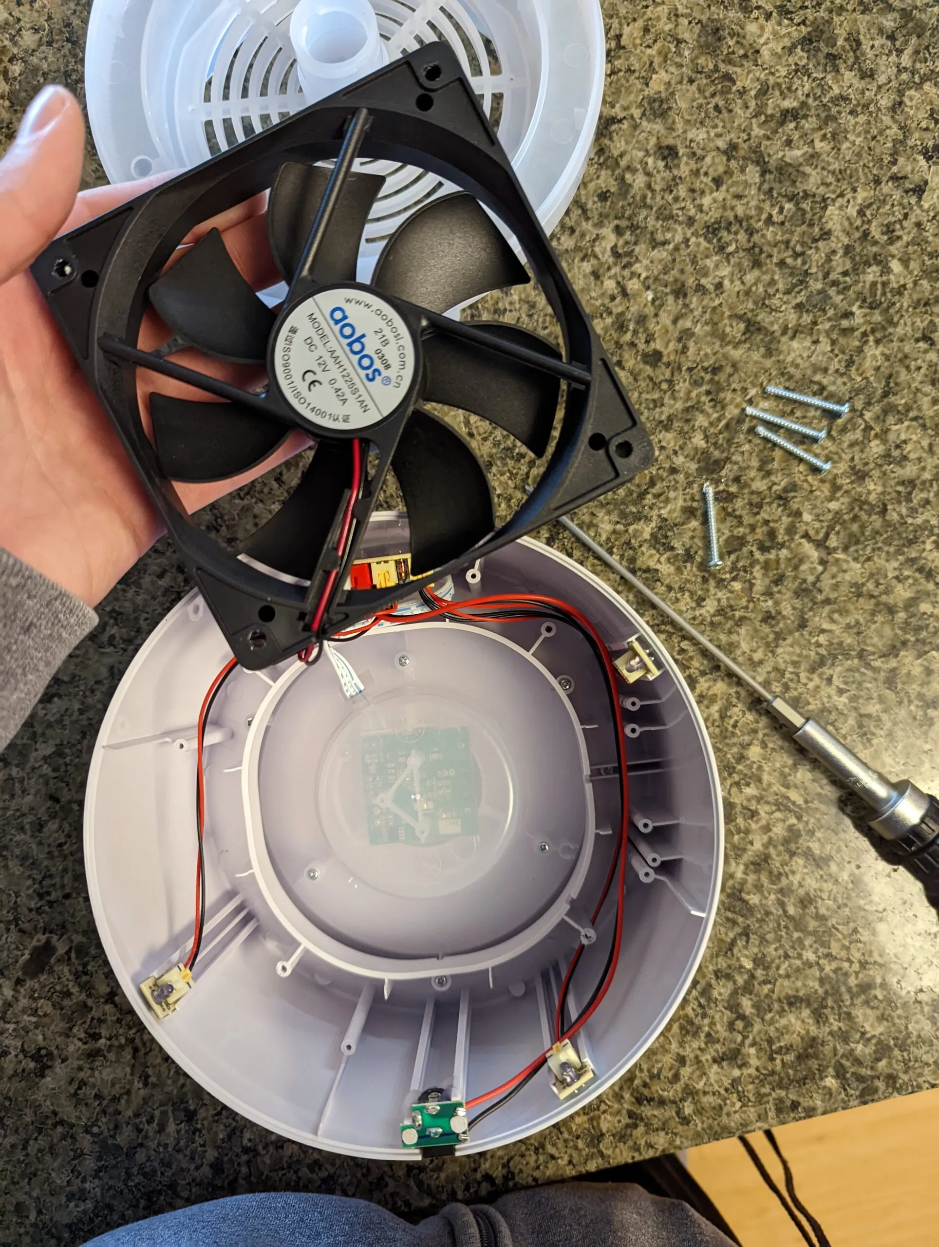
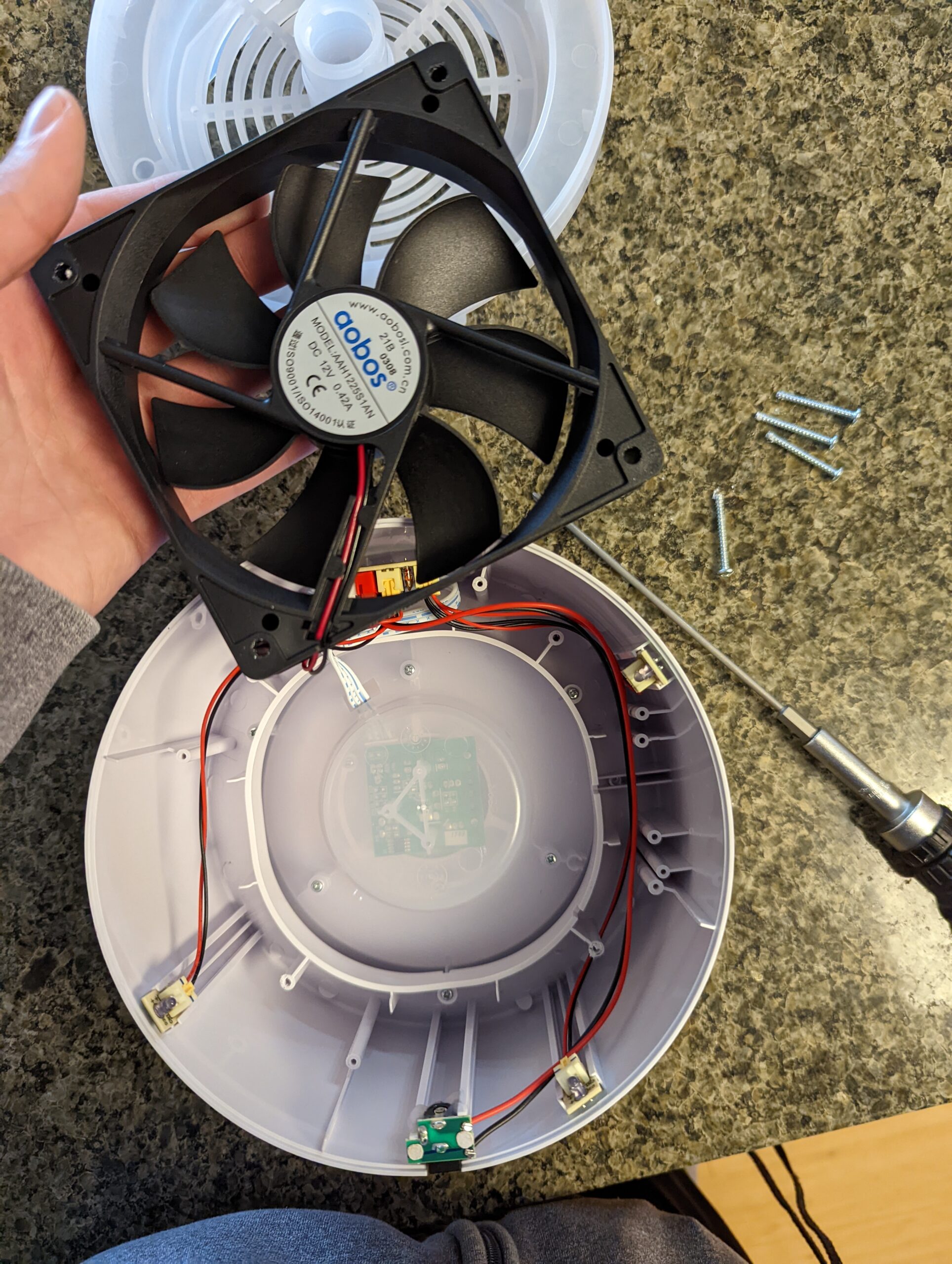
We are going to have to remove that. More screws. With the fan out you can see the control board through the translucent center of the shell.
-
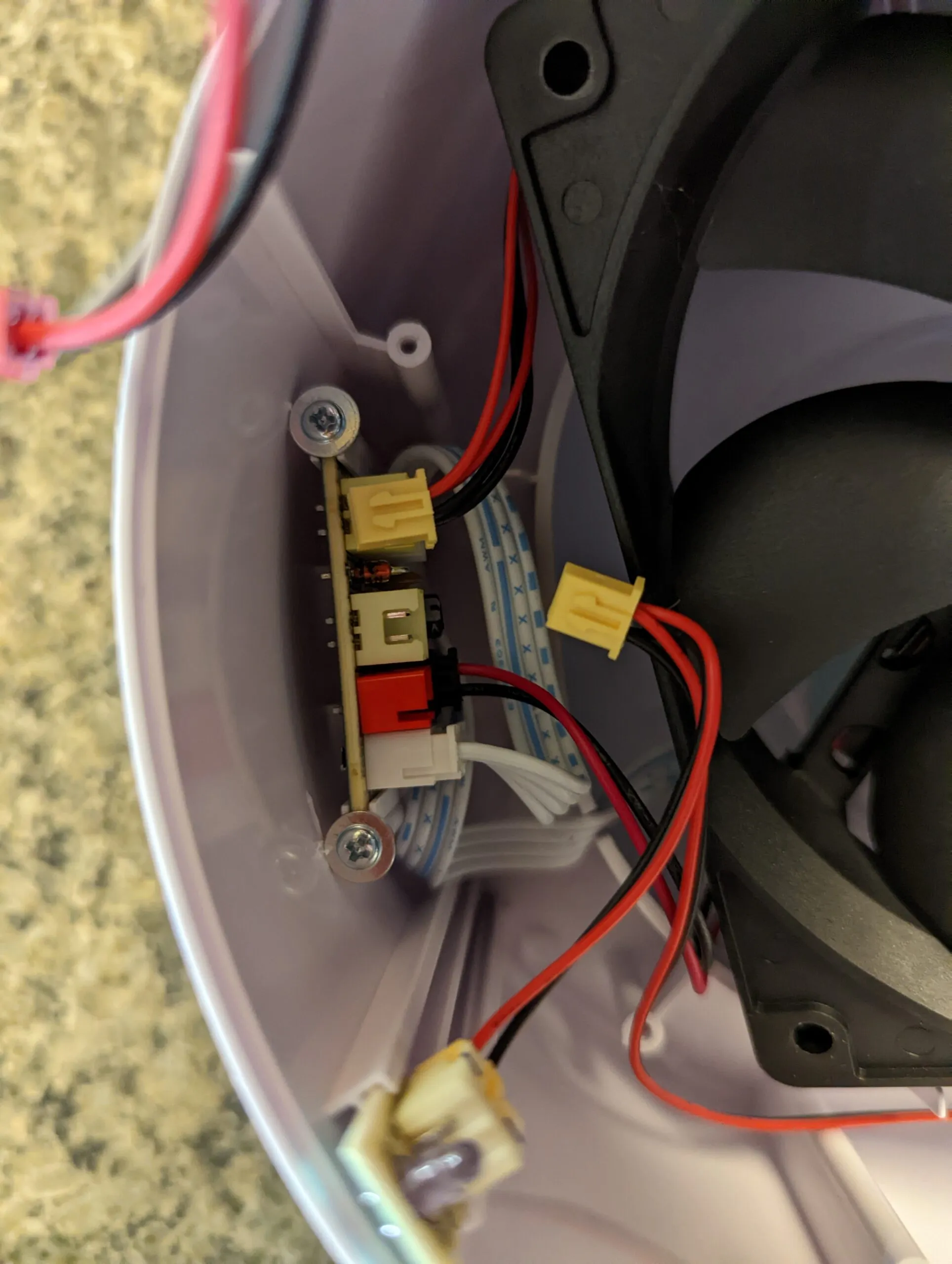
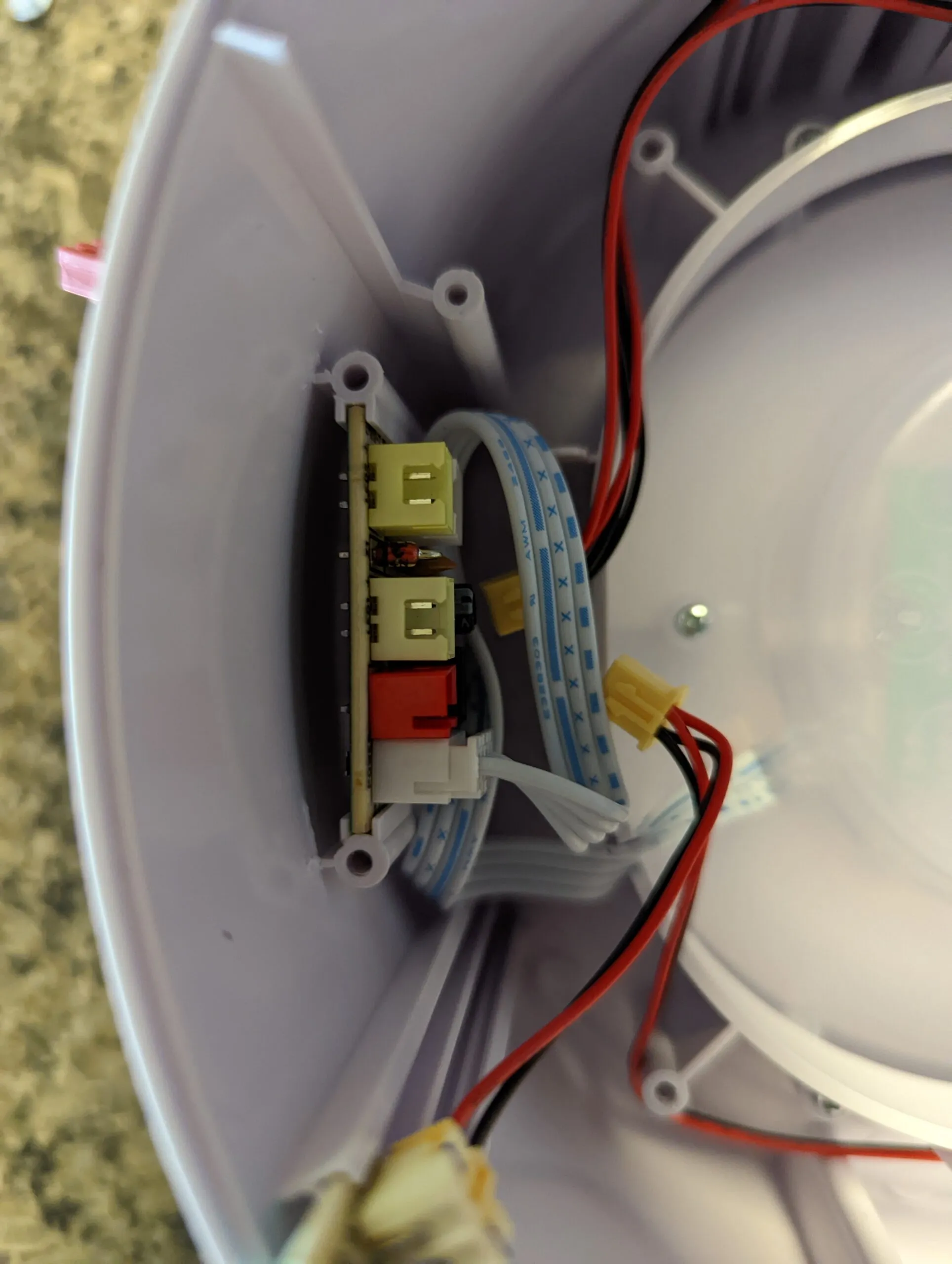
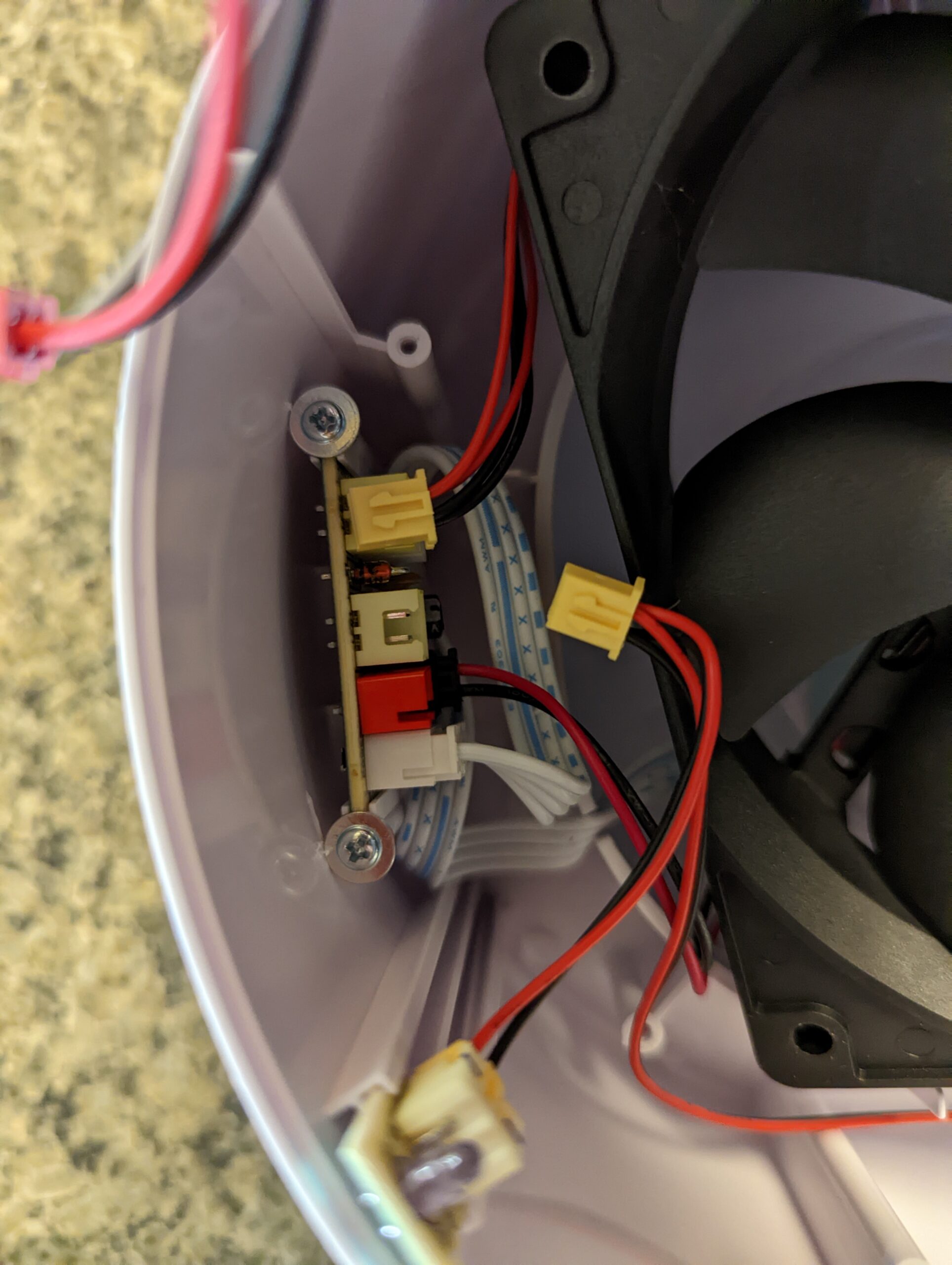
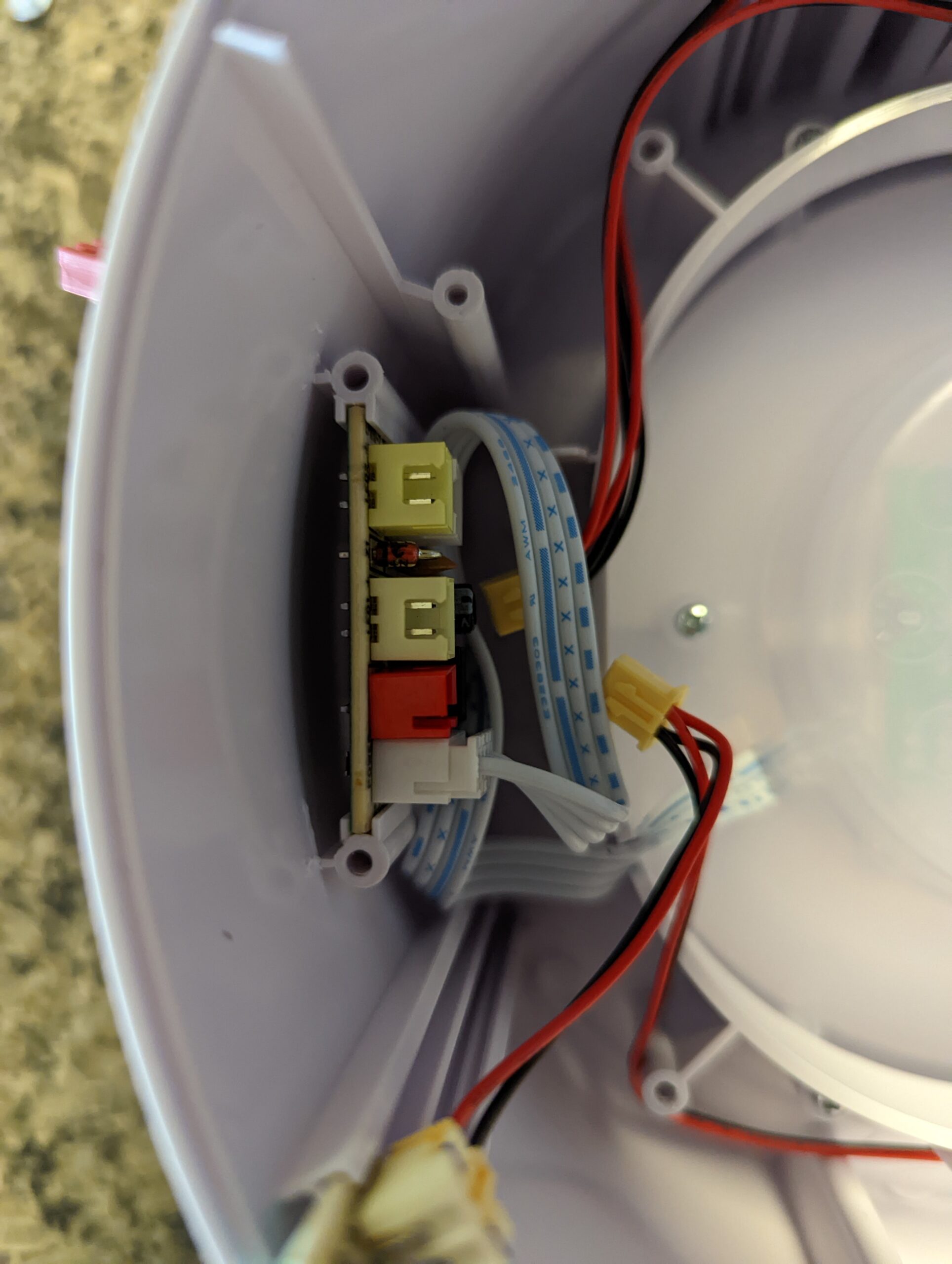
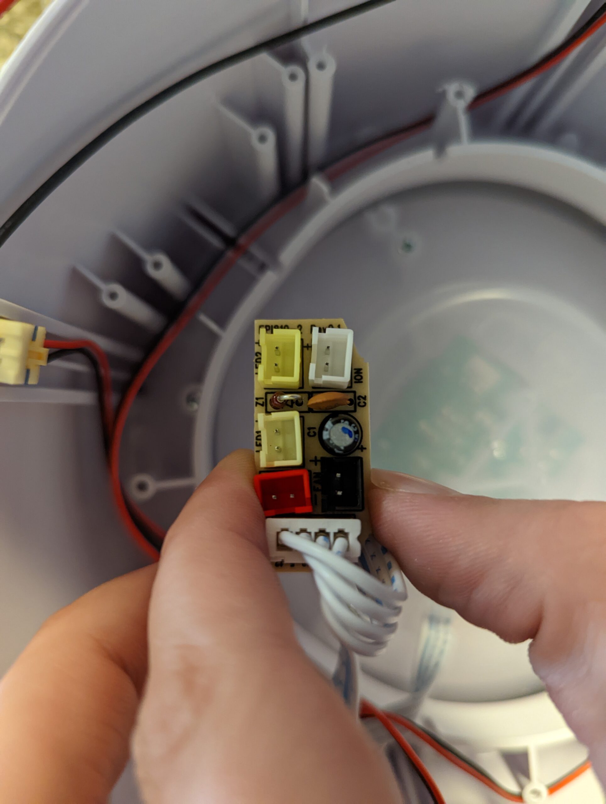
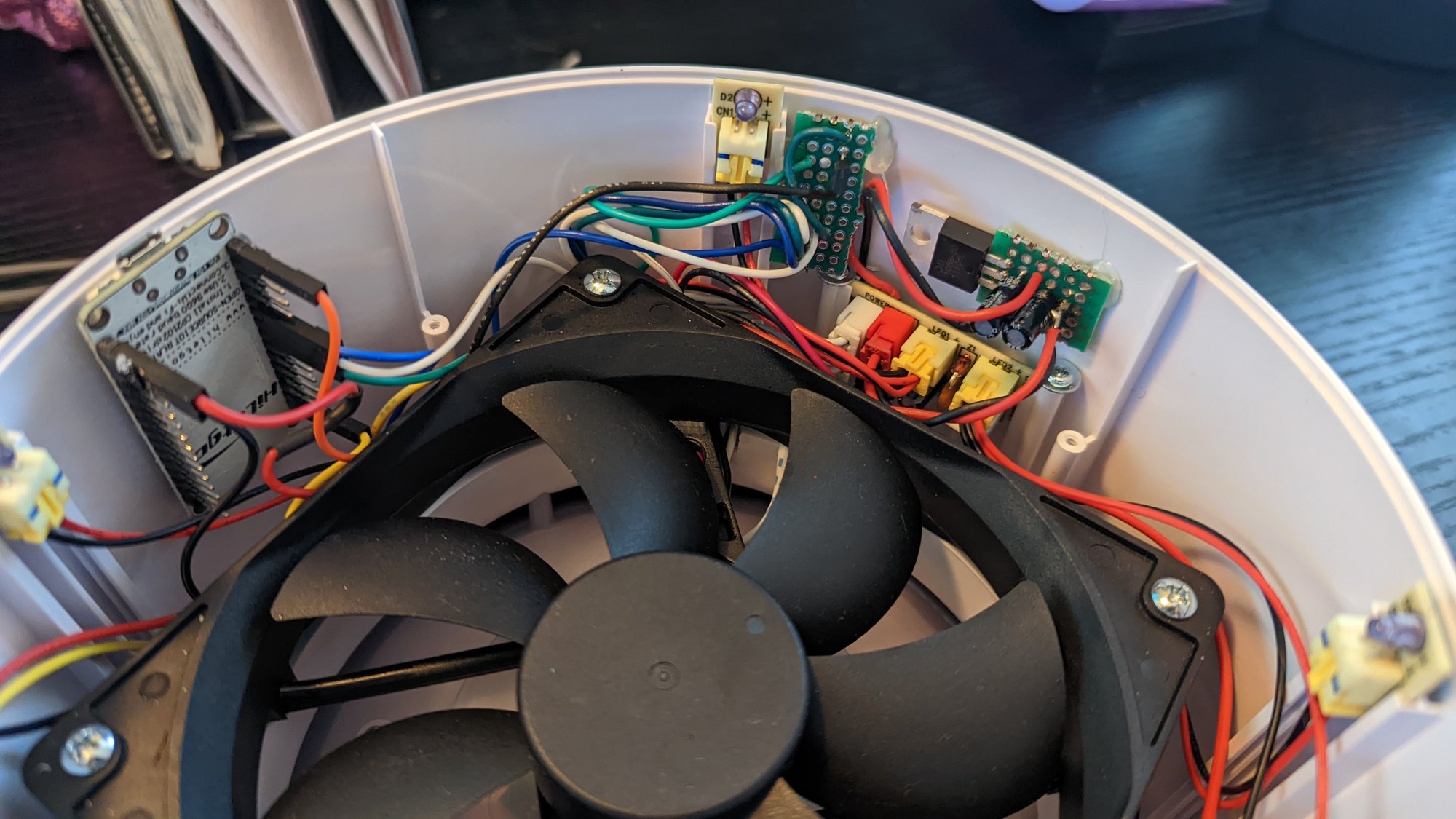
On the distribution PCB we need to unplug the fan, then the LEDs around the translucent ring. Everything in the unit plugs into this one tiny board screwed to the shell wall.
-
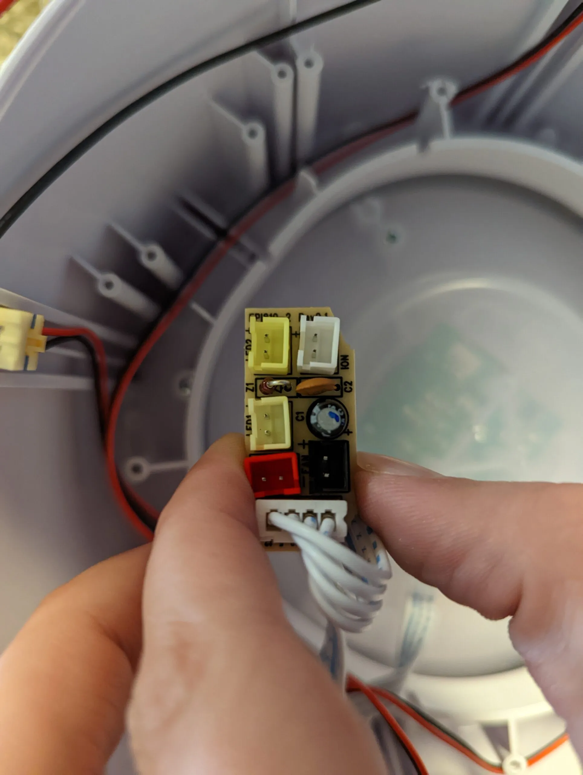
Close-up of the distribution PCB: LED, ION, fan, and control connectors.
-
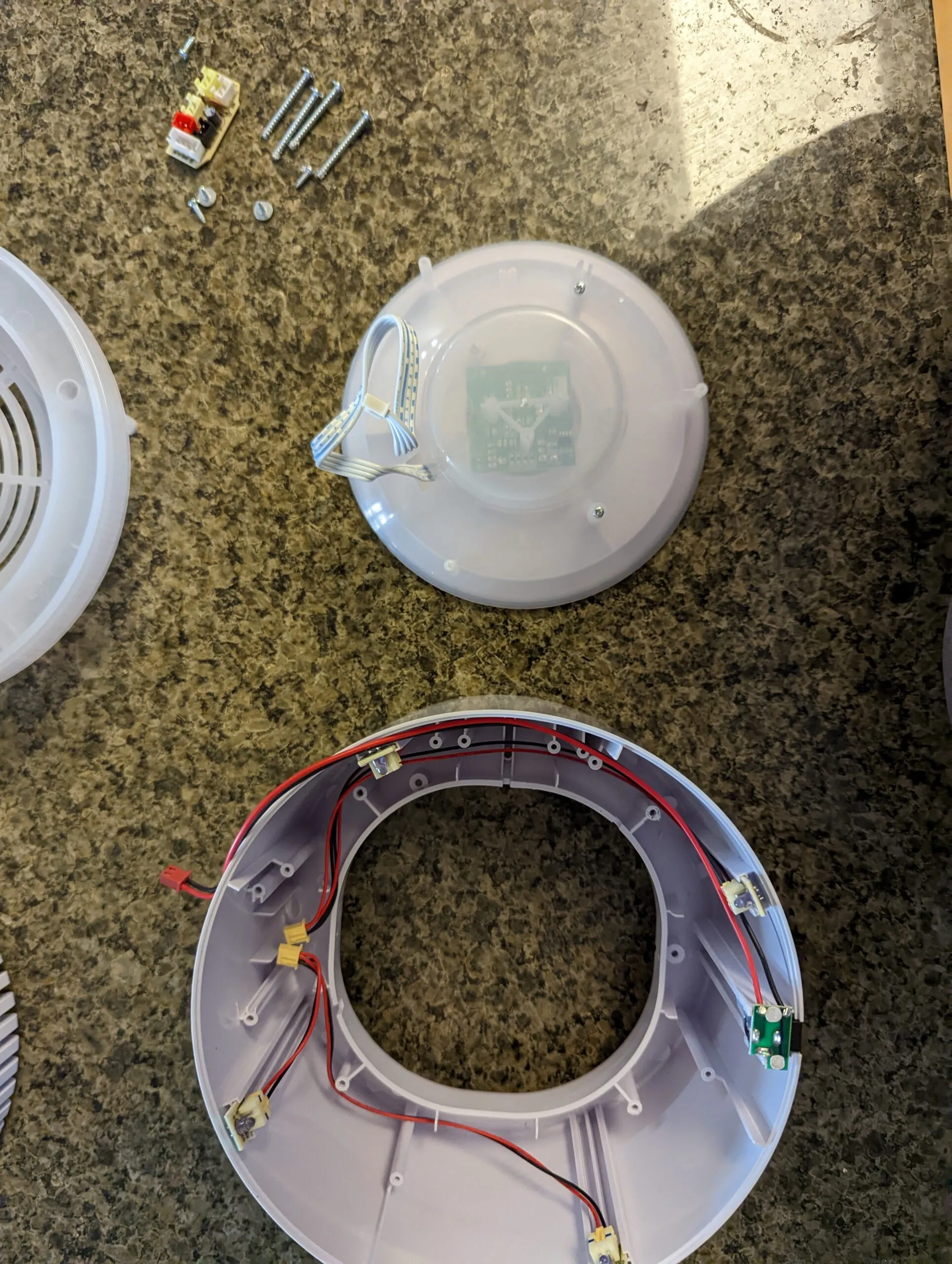
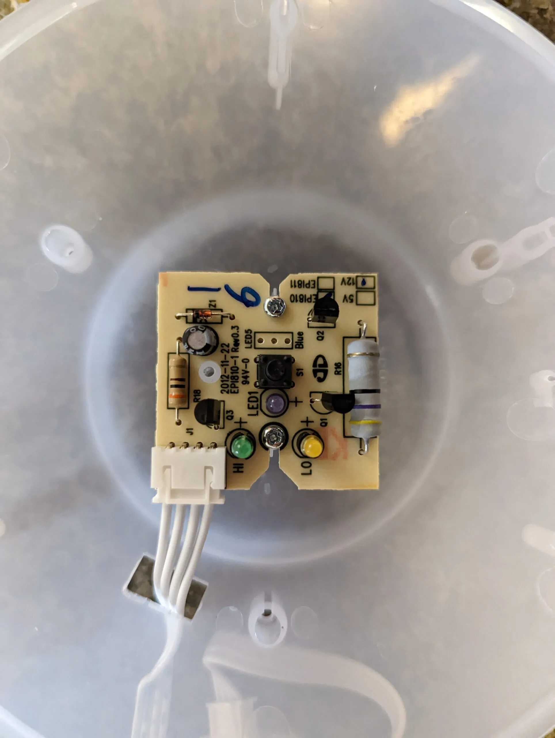
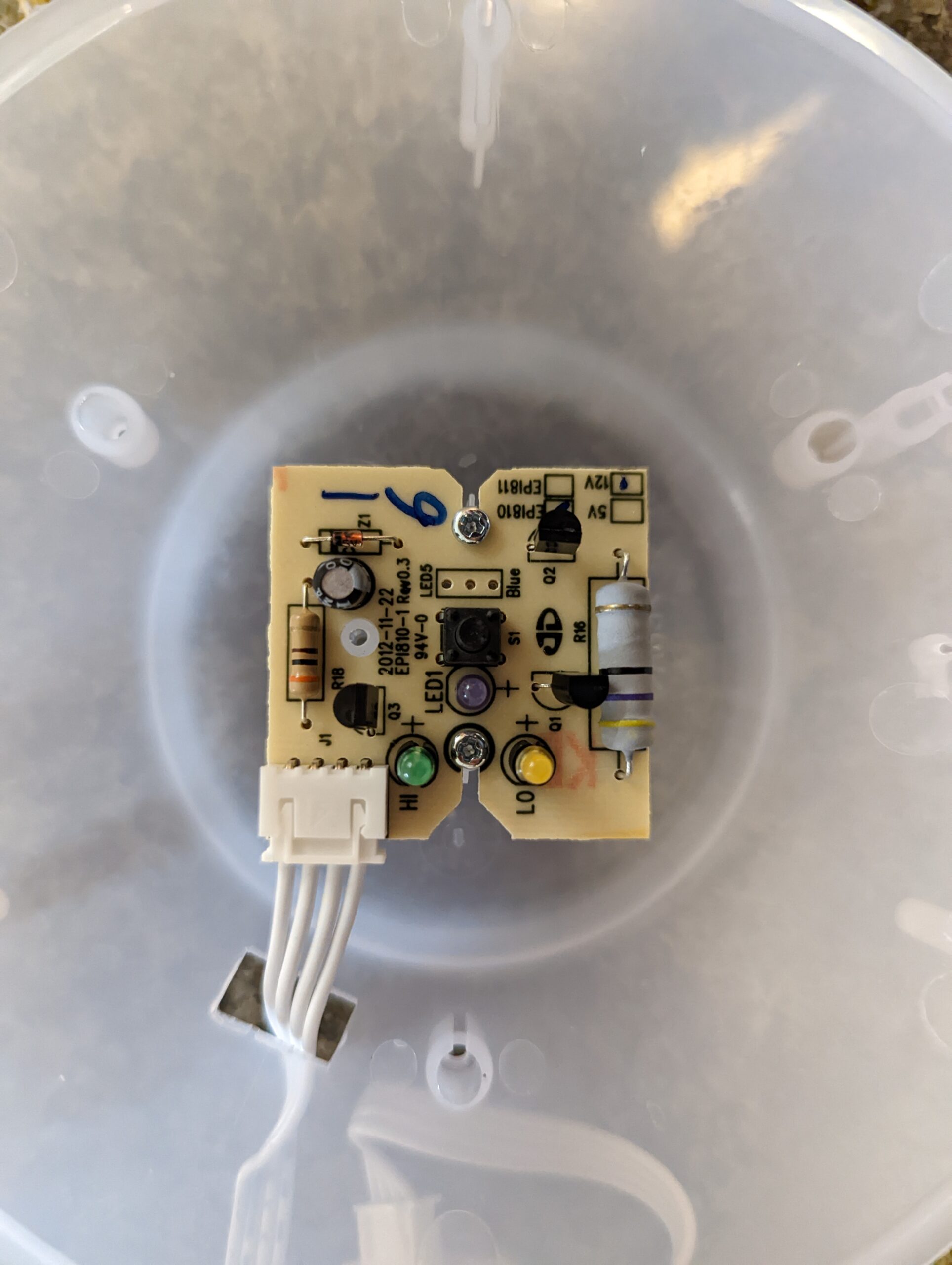
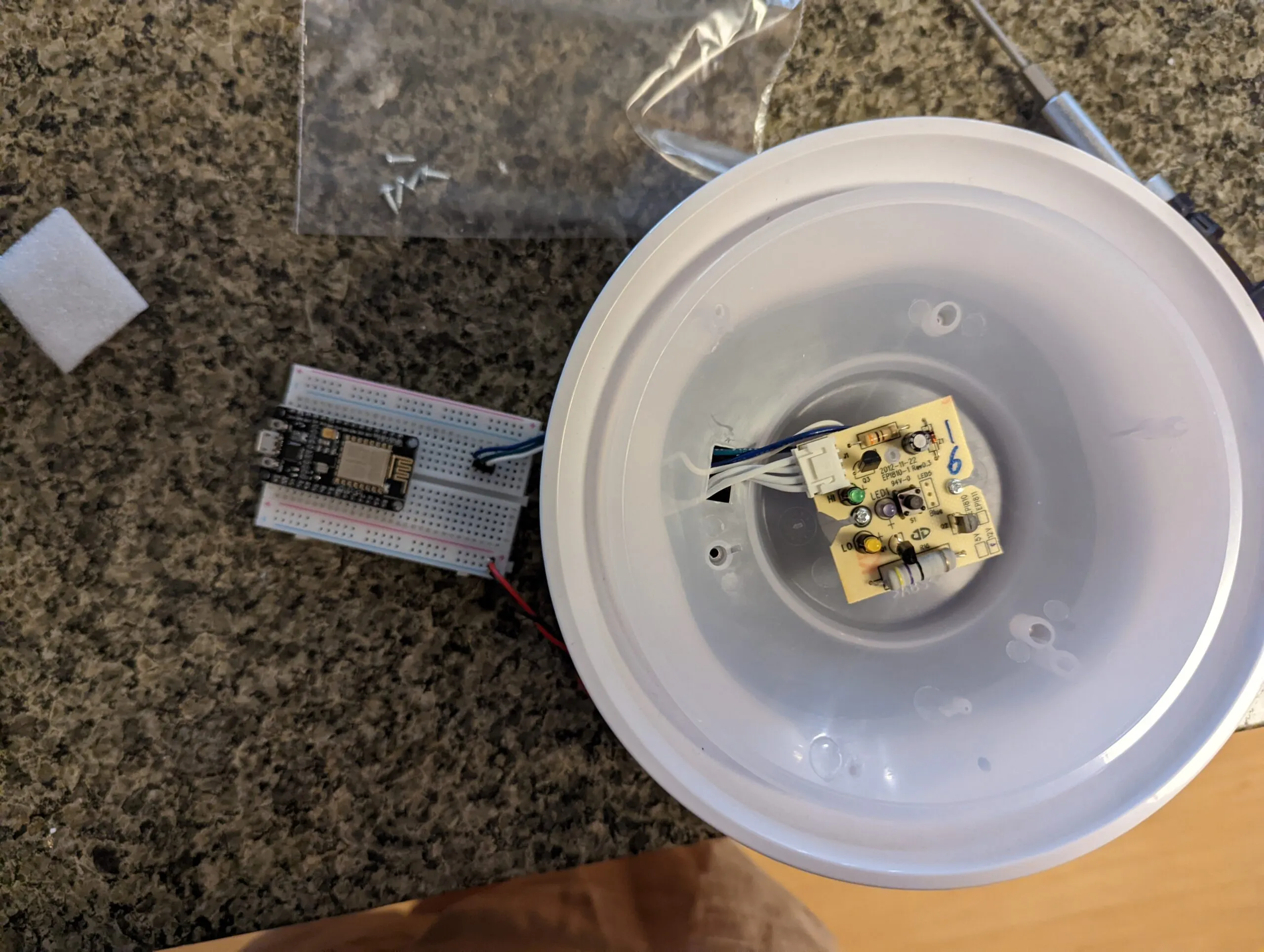
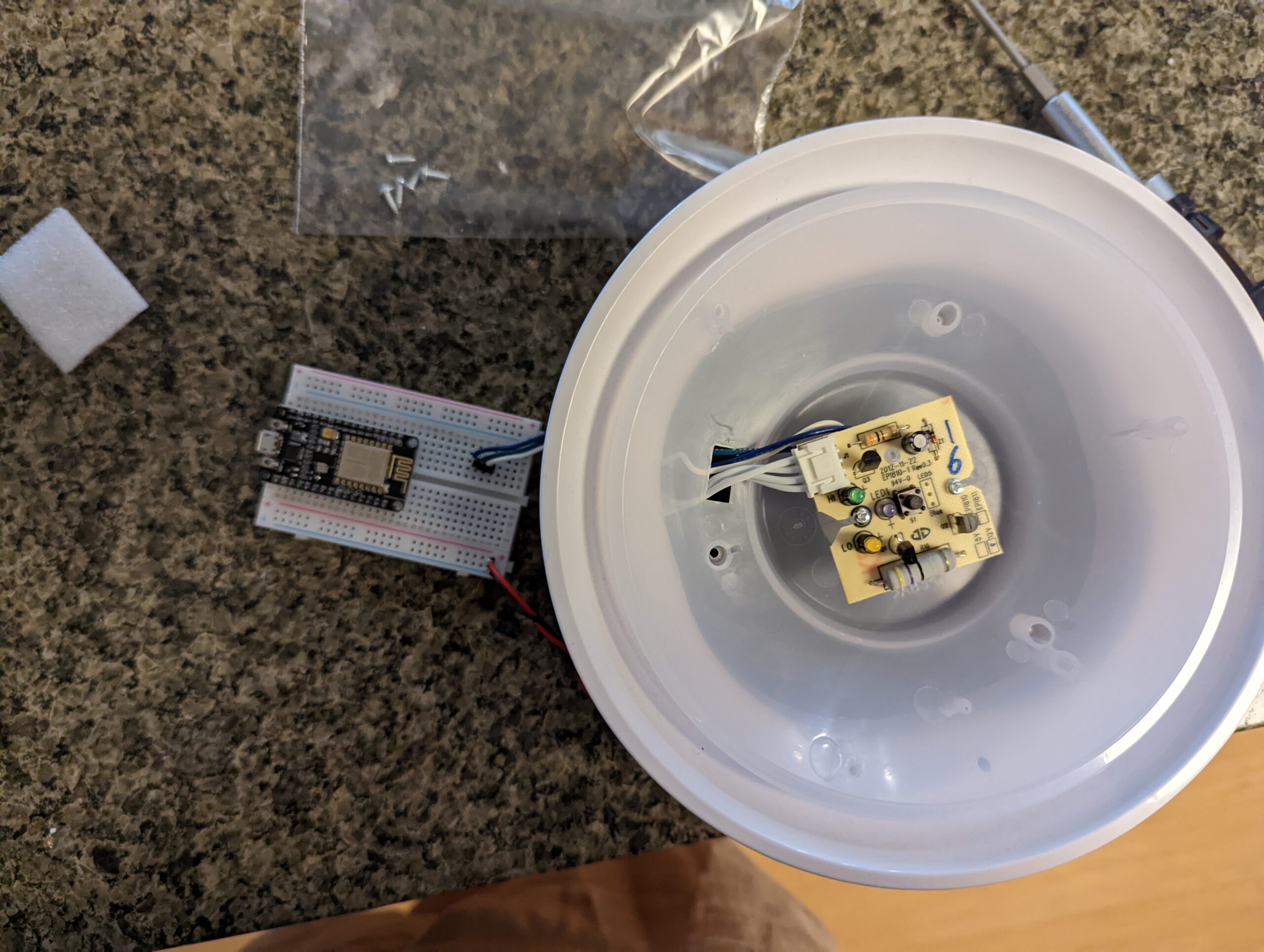
Now we are at the top bit with the control PCB and the user input. Remove the plastic and we have access to the PCB: one button, the HI and LO LEDs, and a 12V / 5V select pad. Everything we need to talk to is on this board.
Signal Extraction
Now that we have access to all of the various pieces, we need to figure out our state and control surface. We could of course strip out the controller and completely replace it but where is the fun in that. Instead, let’s try to use the hardware and control loop that already exists. Our ESP8266 will effectively be a “human” that “presses” the button and “looks” at the LED state.
-
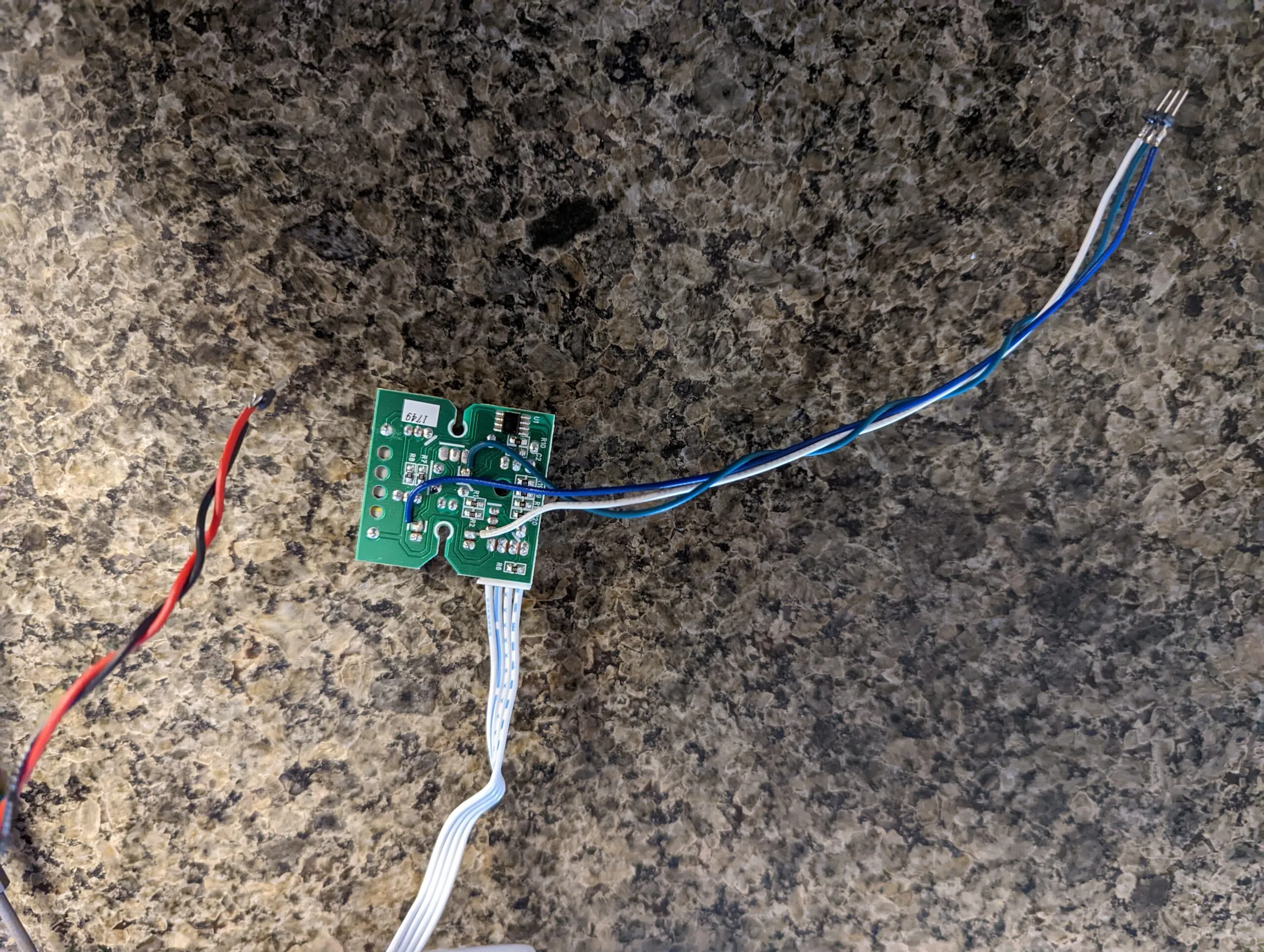
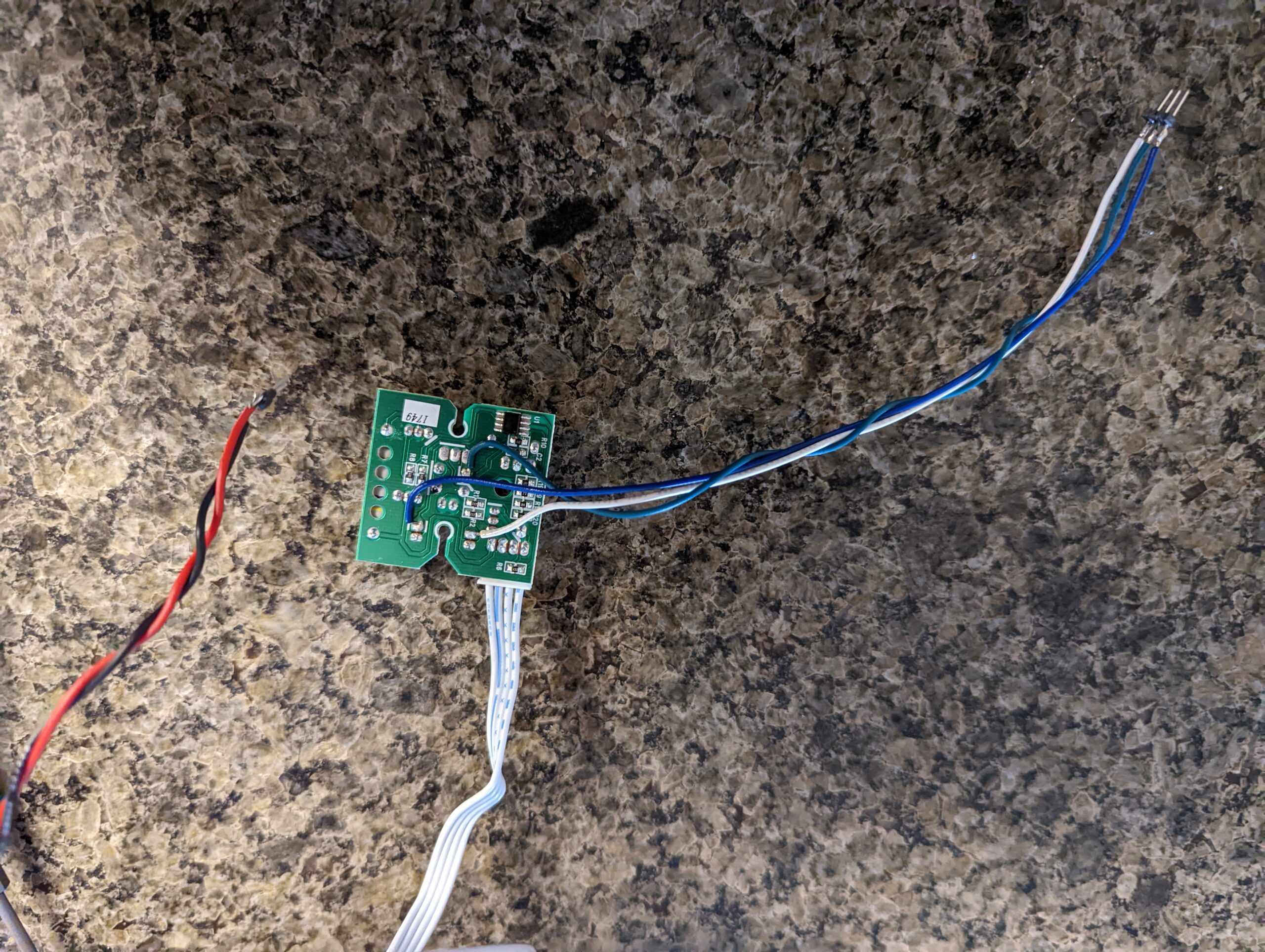
First step, soldering hookup wire to the button and the LEDs (HI and LOW).
We will also tap off power from the input jack (barely visible in the photo) with hookup wire.
-
Next, let’s wire everything up on a solderless breadboard to confirm functionality.
-
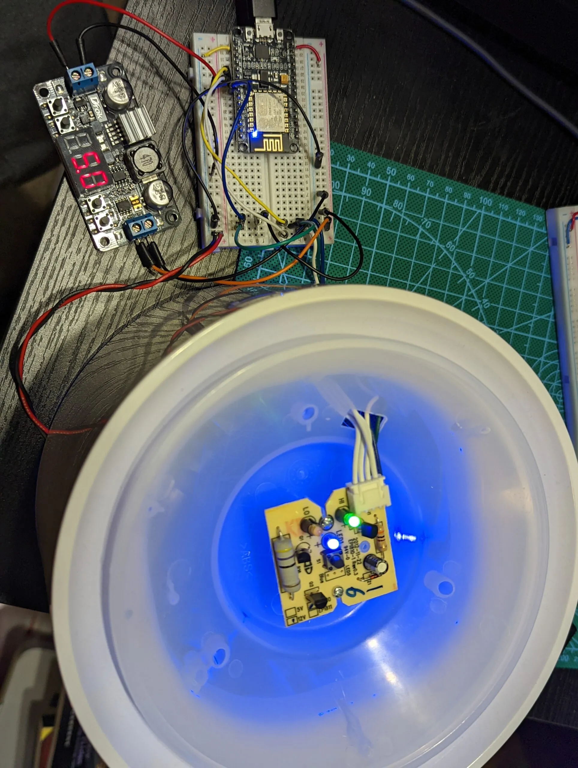
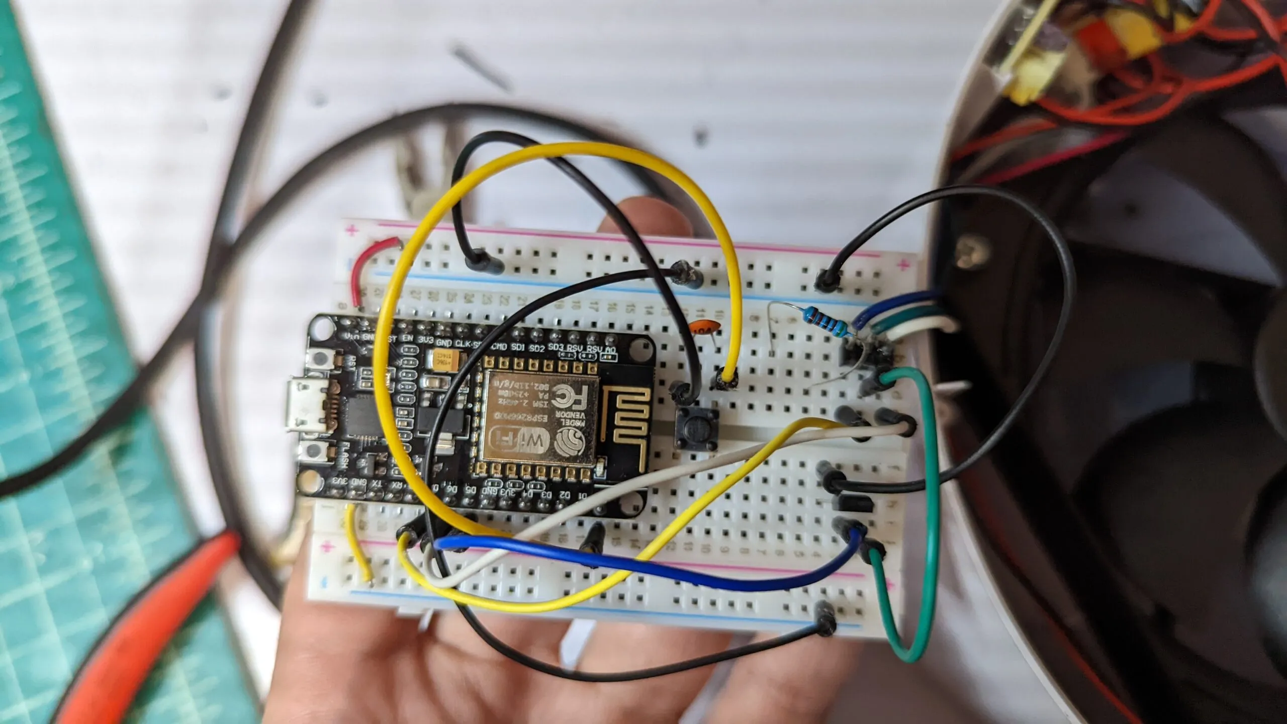
Bunch of wiring later… The buck converter is reading 5.0V and the dome LEDs are lit, so the ESP is driving the original board.
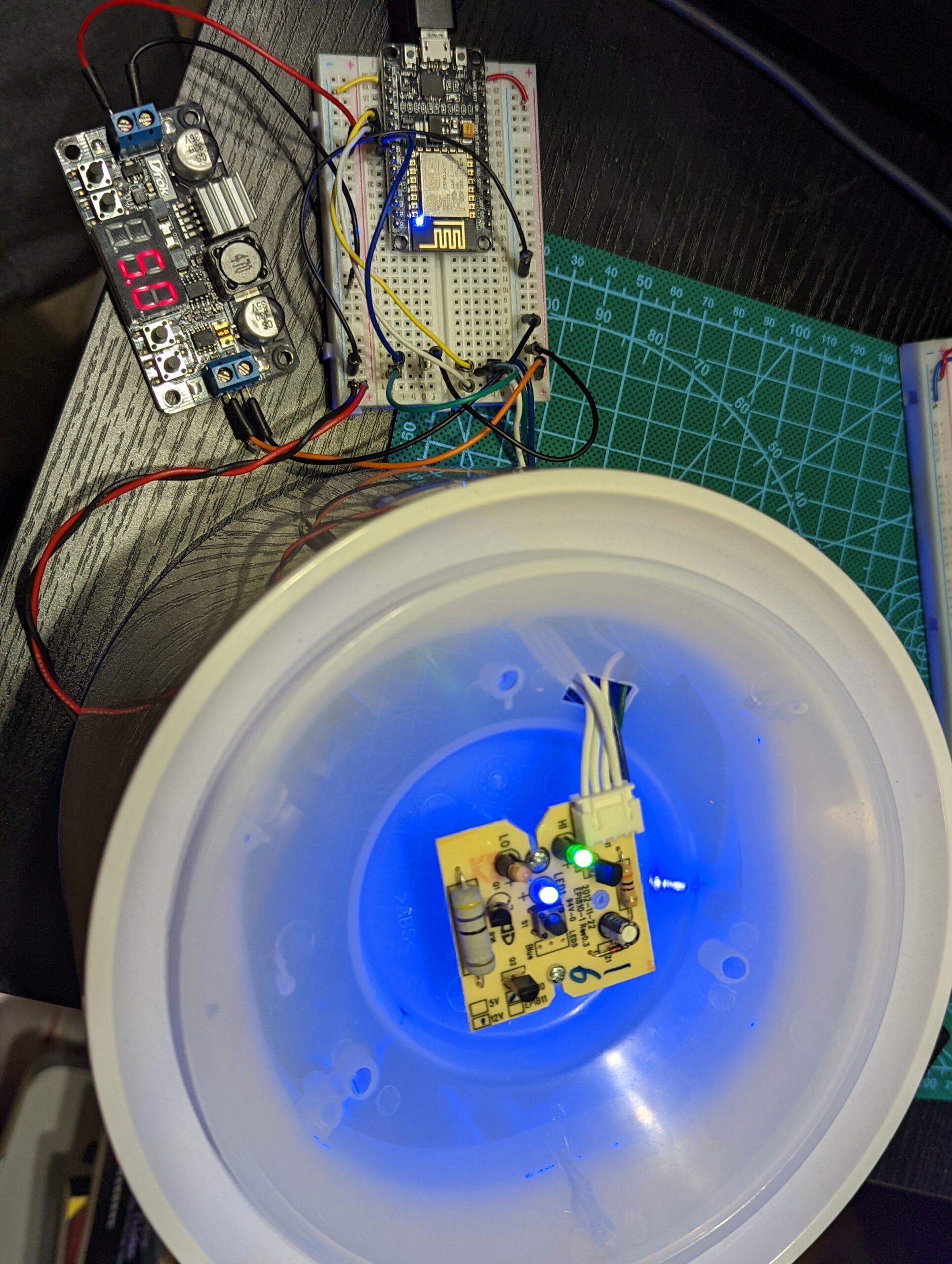
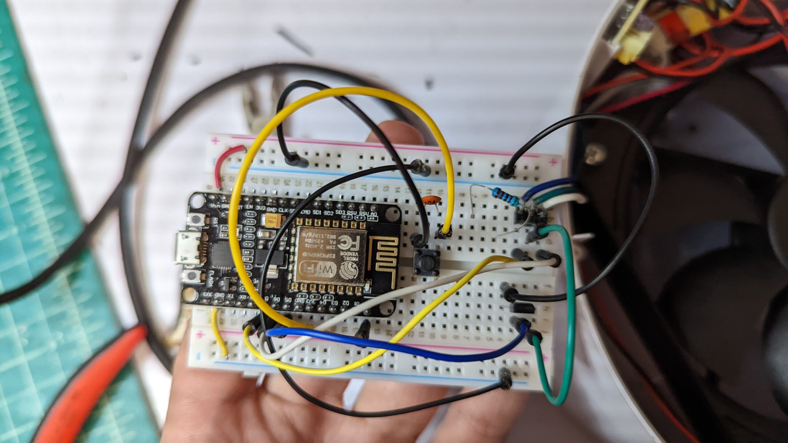
Okay, so what have we learned:
- Voltage in needs to be stepped down from 12V to 5V for ESP8266 supply
- We can directly read the LED voltage state as digital inputs
- We need a RESET button for the ESP8266
- This is just standard when we are configuring Wi-Fi / IOT things
- We can use a MOSFET to short the button signal to ground to emulate a button press
- And we can release it to emulate the button release
Stuffing the Enclosure
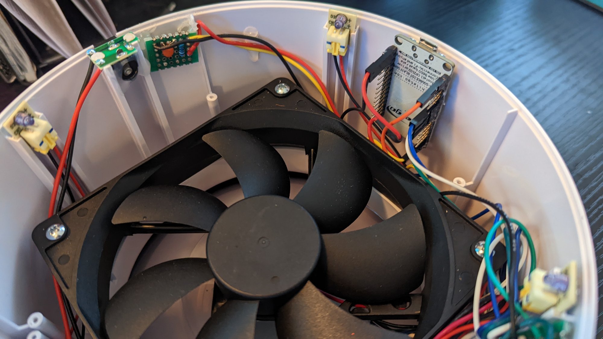
Everything I just prototyped needs to be stuffed inside the existing enclosure. Fortunately there is some gap between the fan and the enclosure wall. Unfortunately, we will not be stuffing the solderless breadboard directly.
-
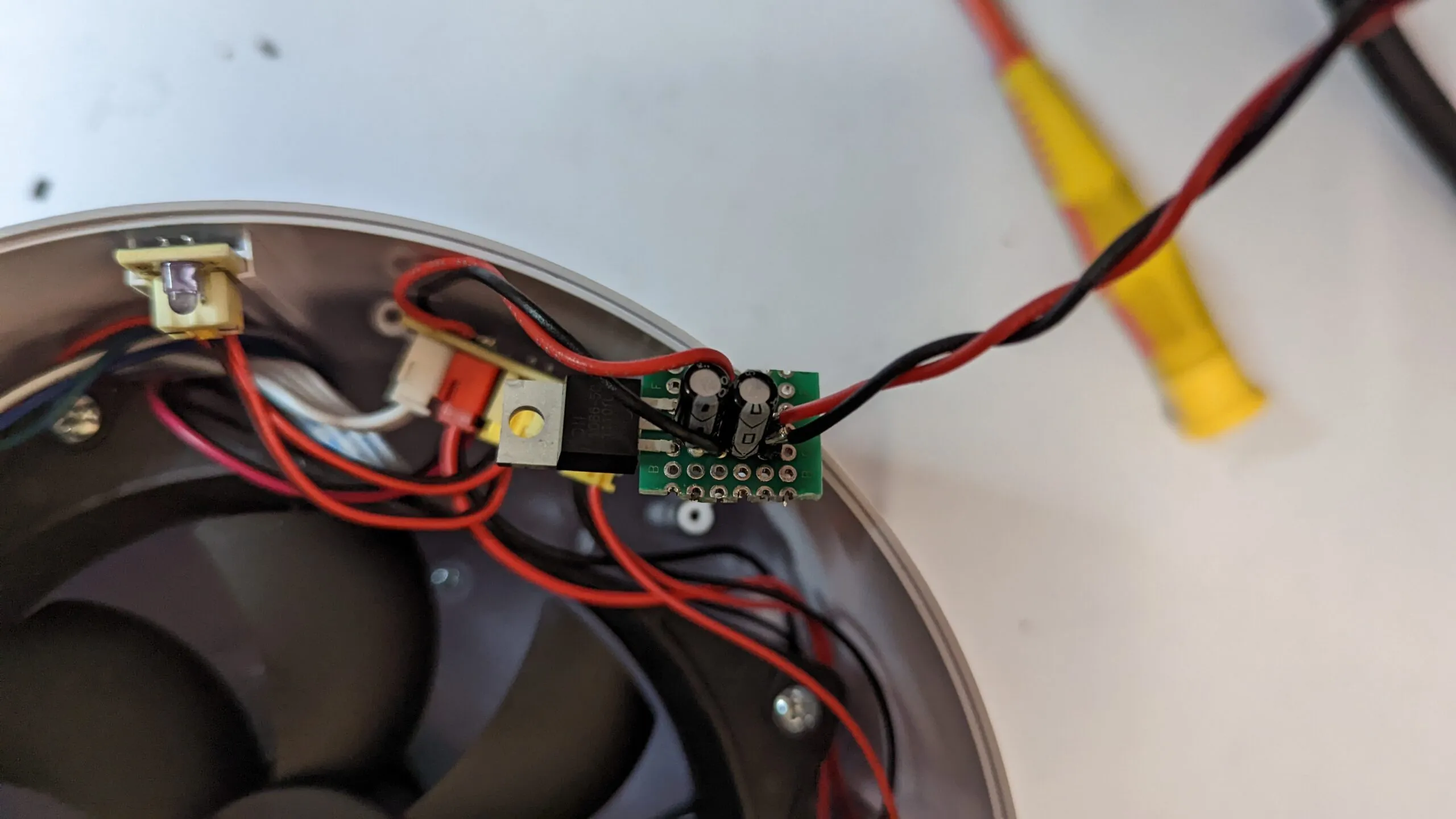
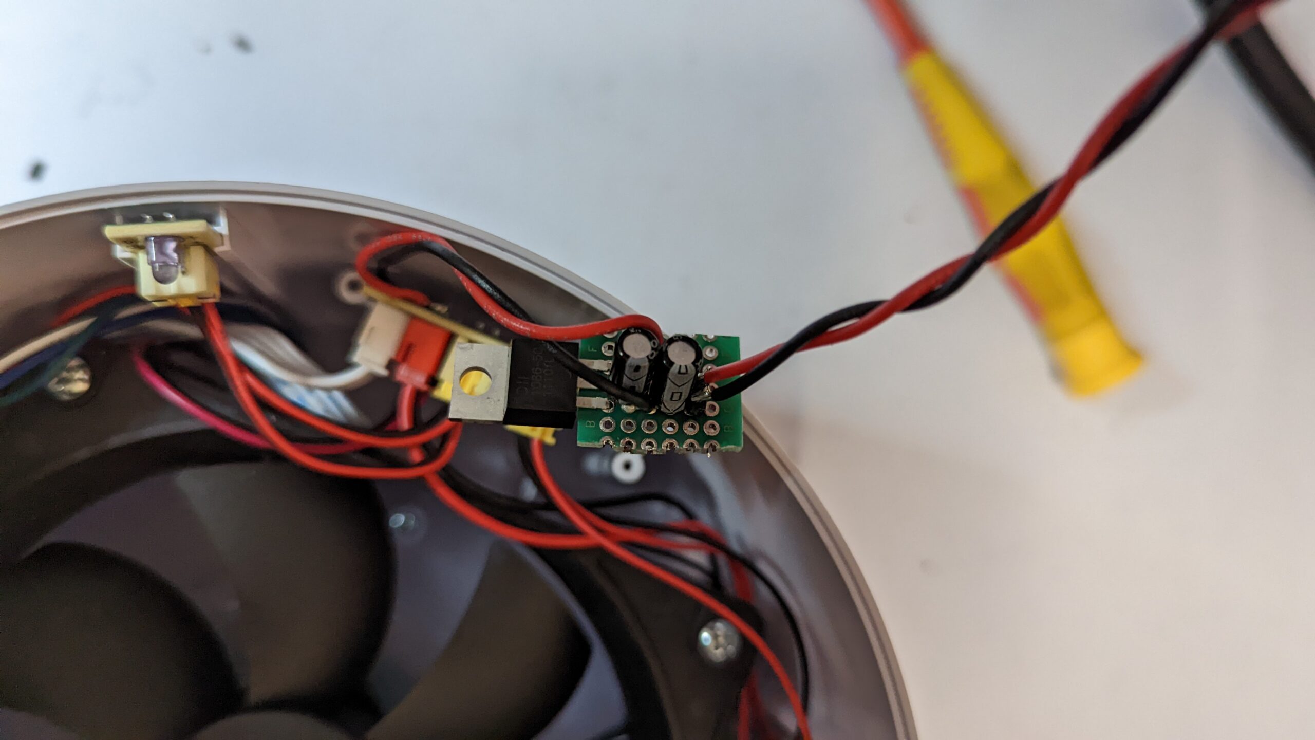
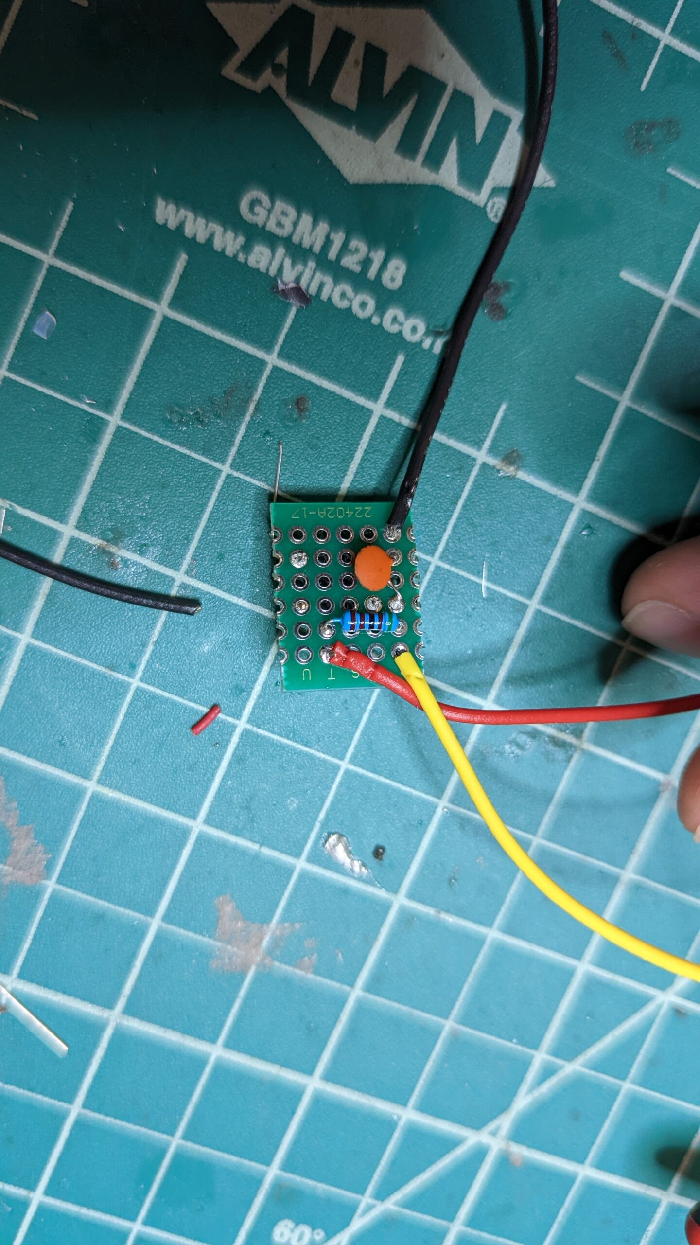
First step, let’s build a step-down power regulator. A regulator and two caps on a scrap of perfboard is all it takes.
-
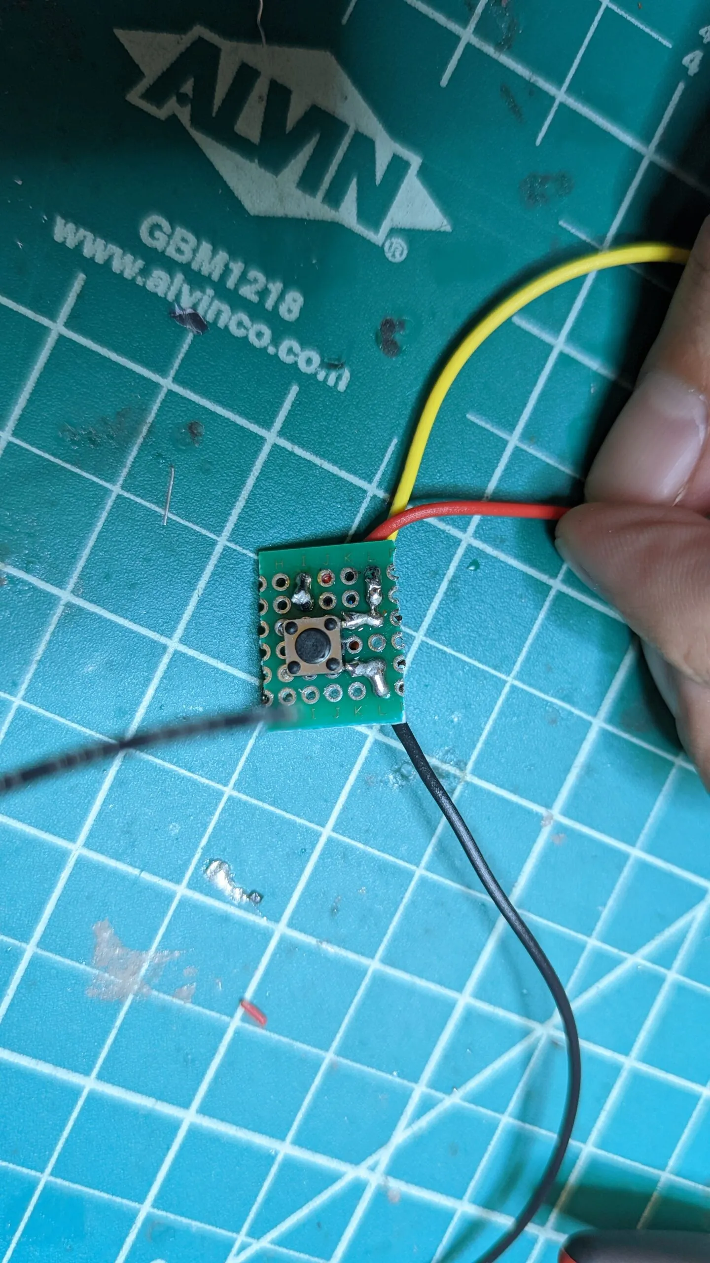
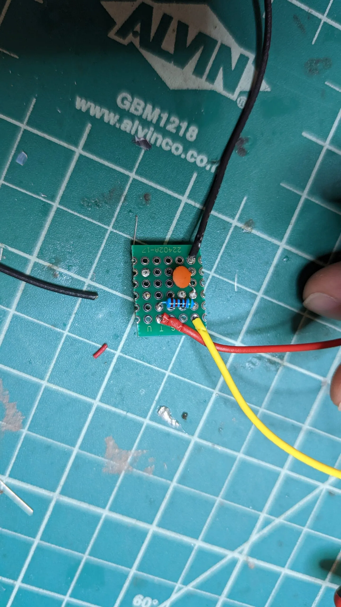
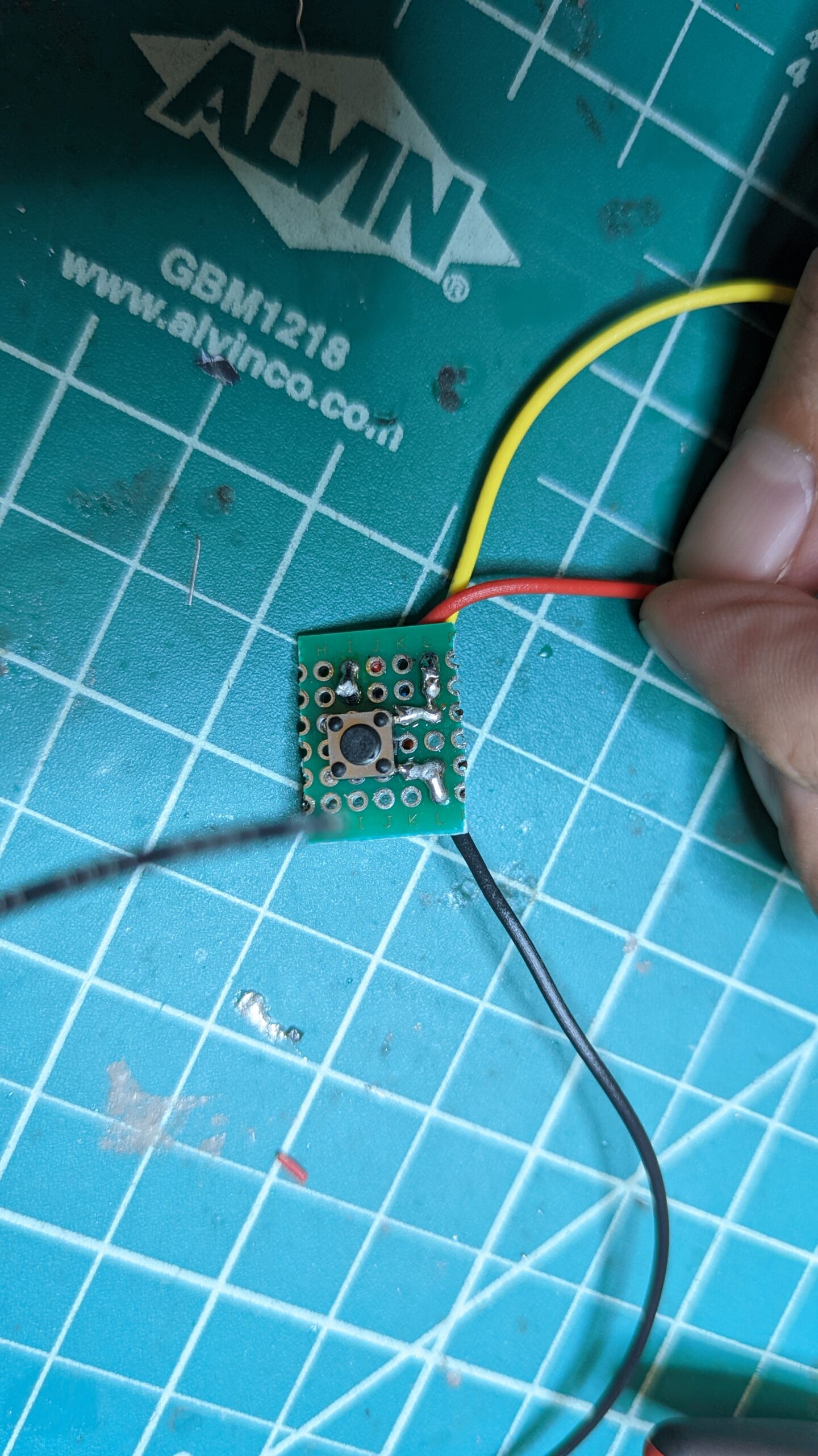
Next let’s build a little PCB for the reset button. We will drill a hole into the enclosure and secure this PCB with a bit of hot glue. On the back there is a pull-up resistor and a small cap for debounce.
-
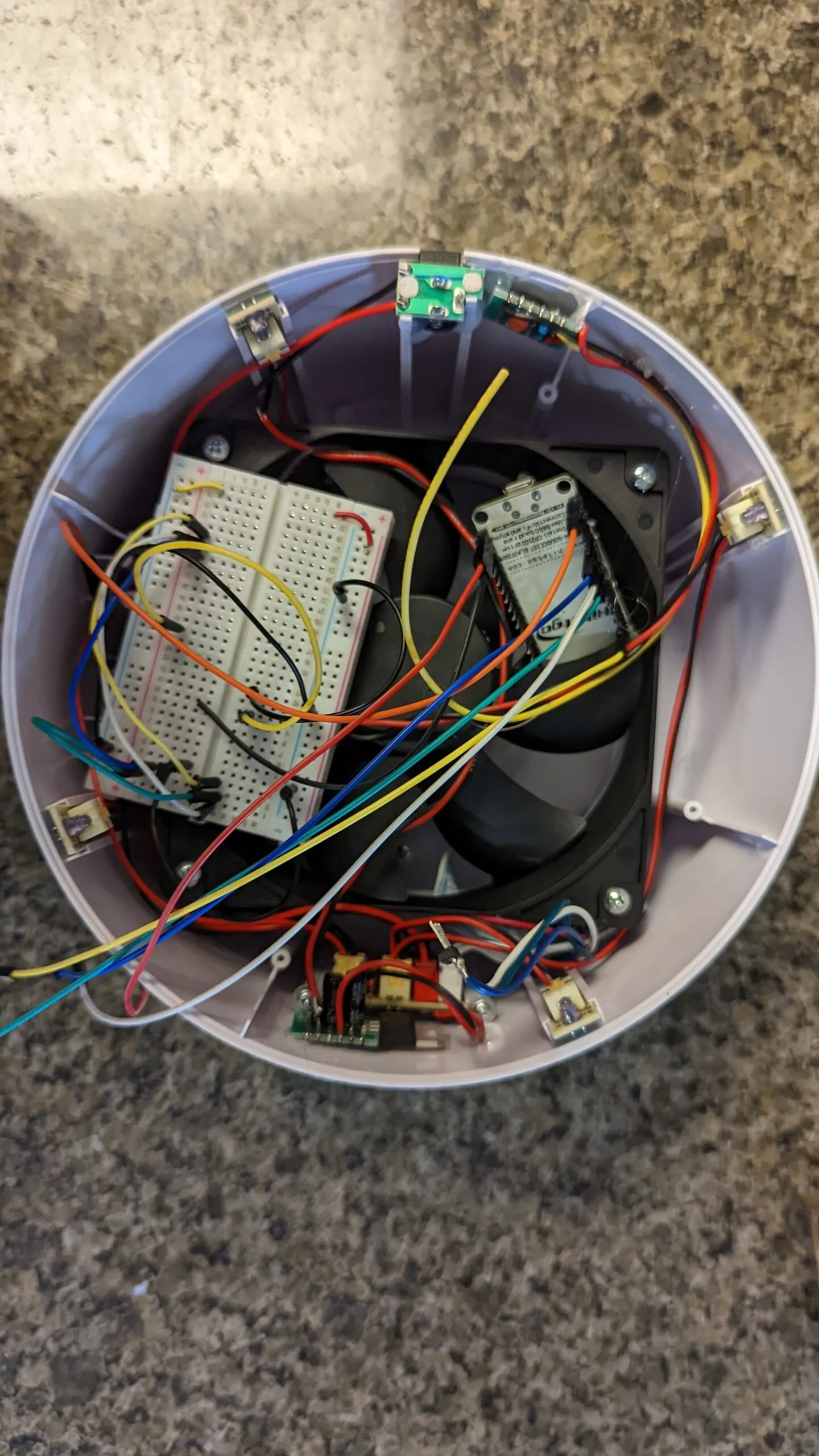
Now we just need to translate the wiring from the breadboard into pin hookup on the ESP8266. The breadboard sits in the shell for reference while the jumpers move over one at a time.
-
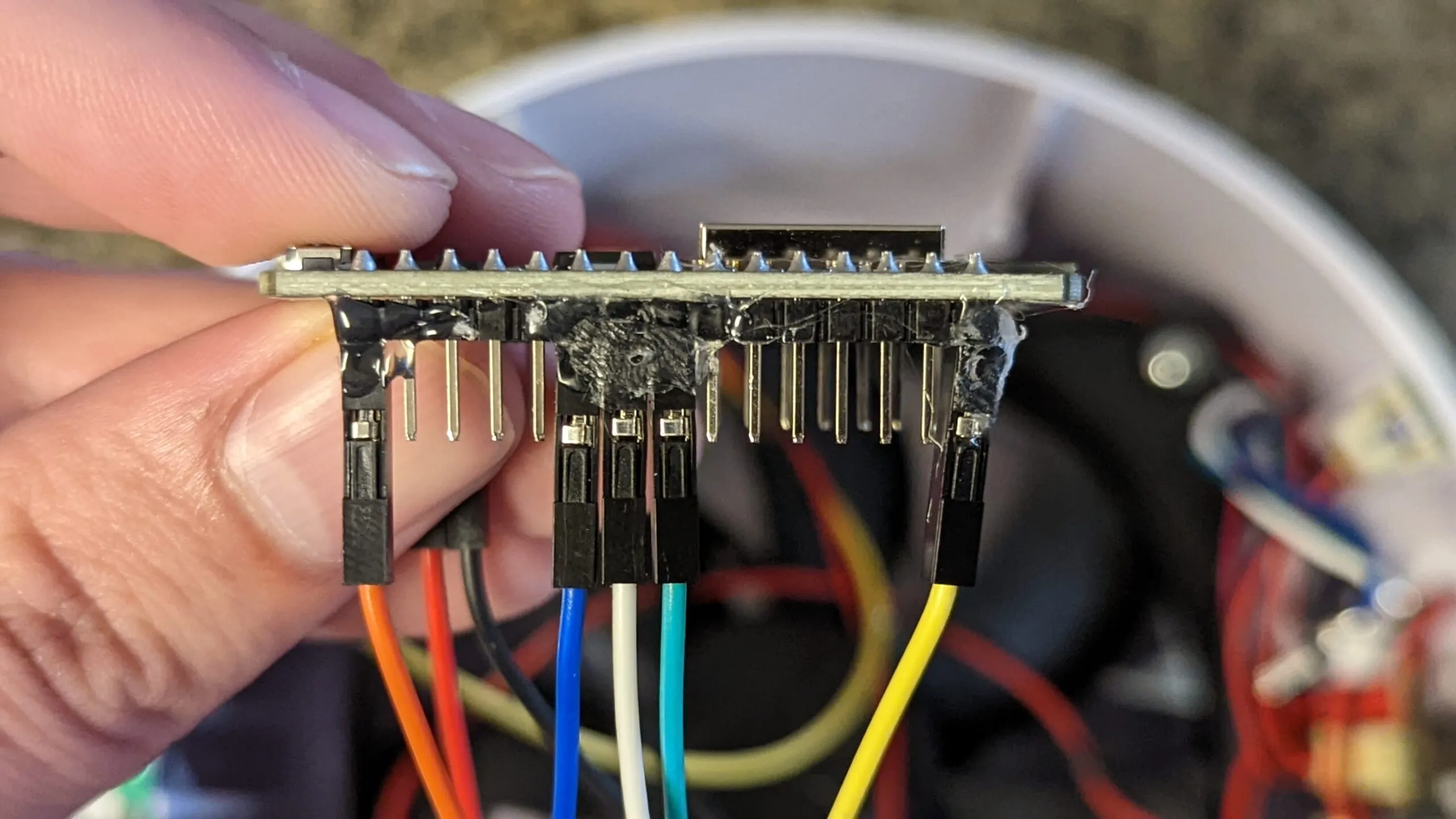
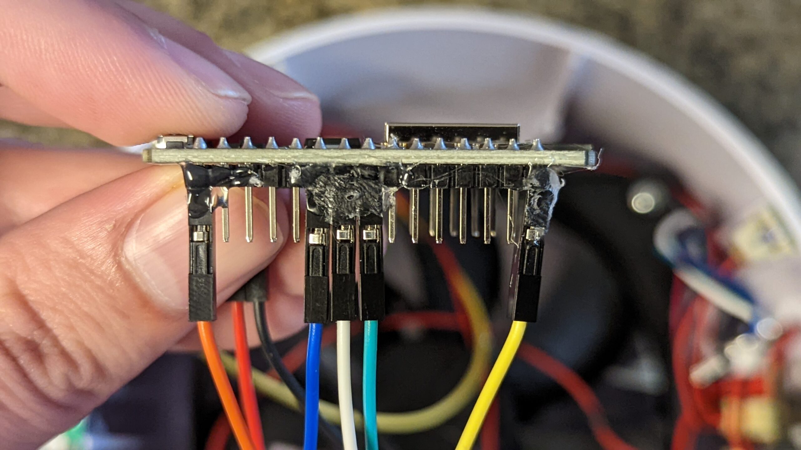
Done. And it has some hot glue for good measure. The fan will be vibrating right next to these headers, so the jumpers get glued in.
-
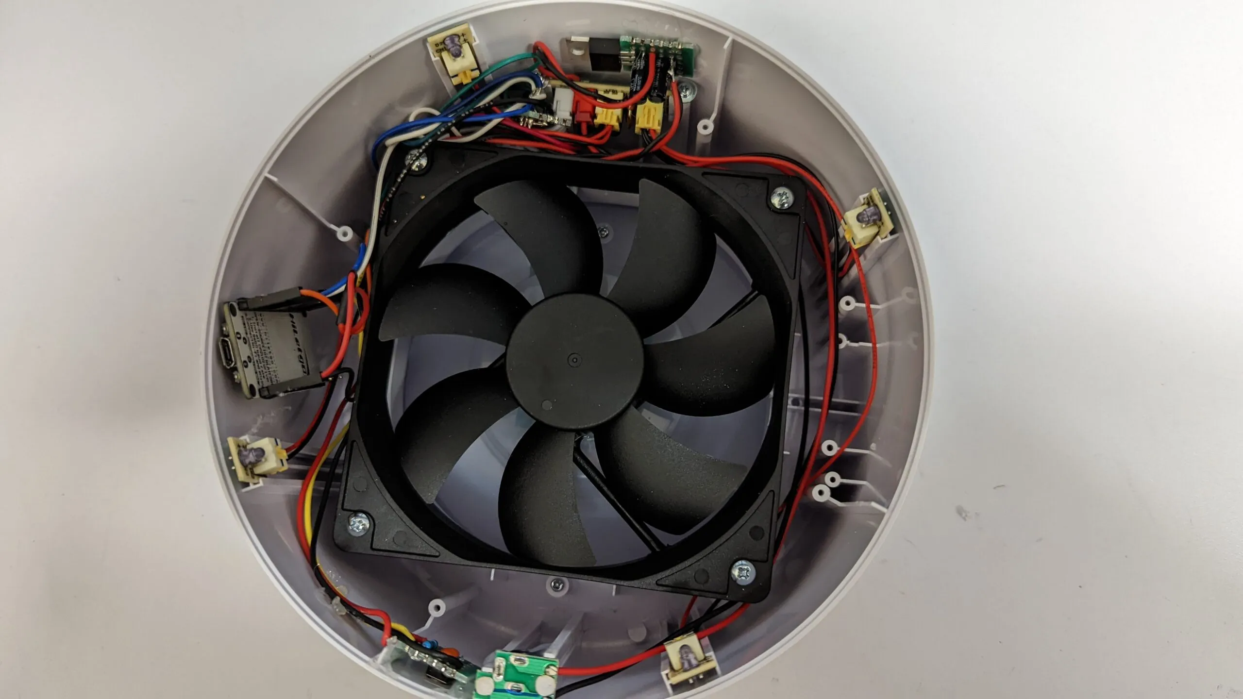
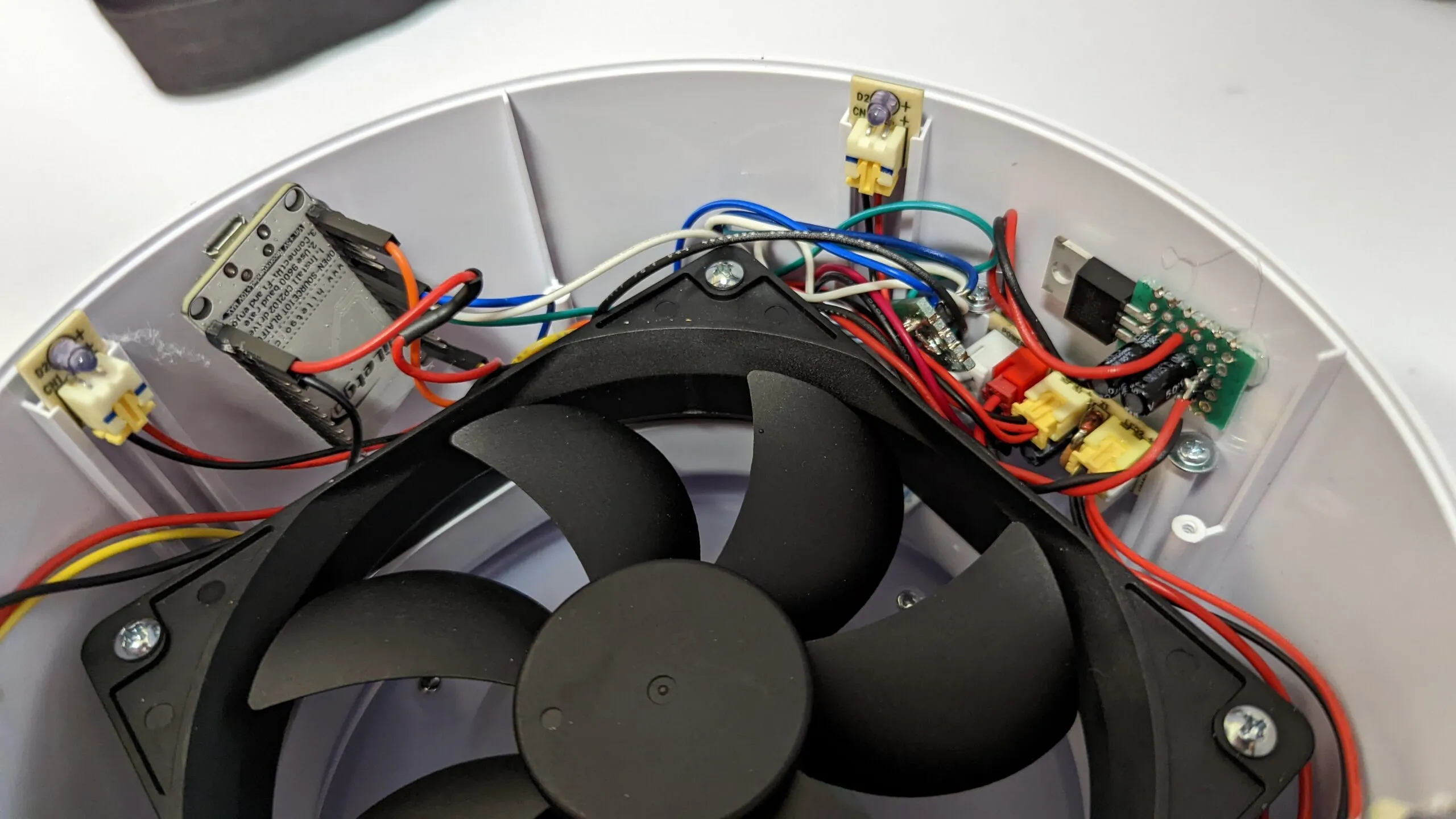
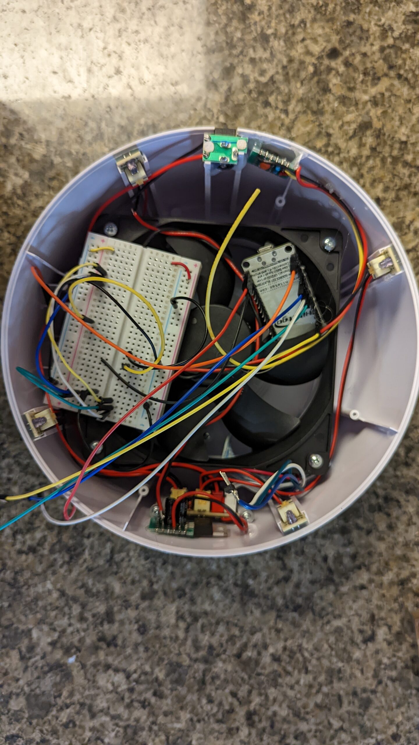
Stuffing everything in. Wiring should be as neat as possible. Making sure to plug all the connectors into the distribution PCB properly.
-
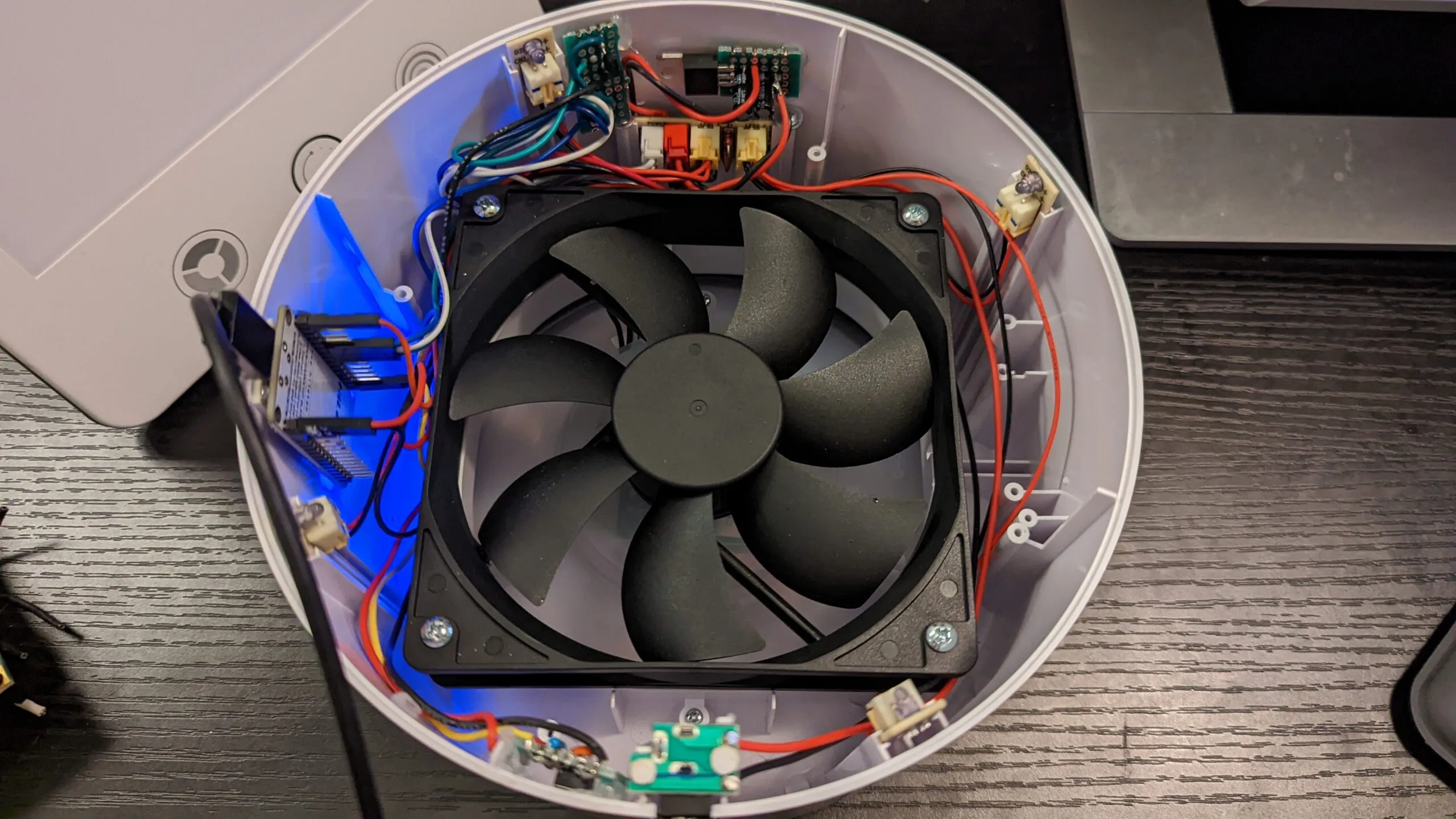
Before we close this up, we need to flash the firmware (which will be discussed later).
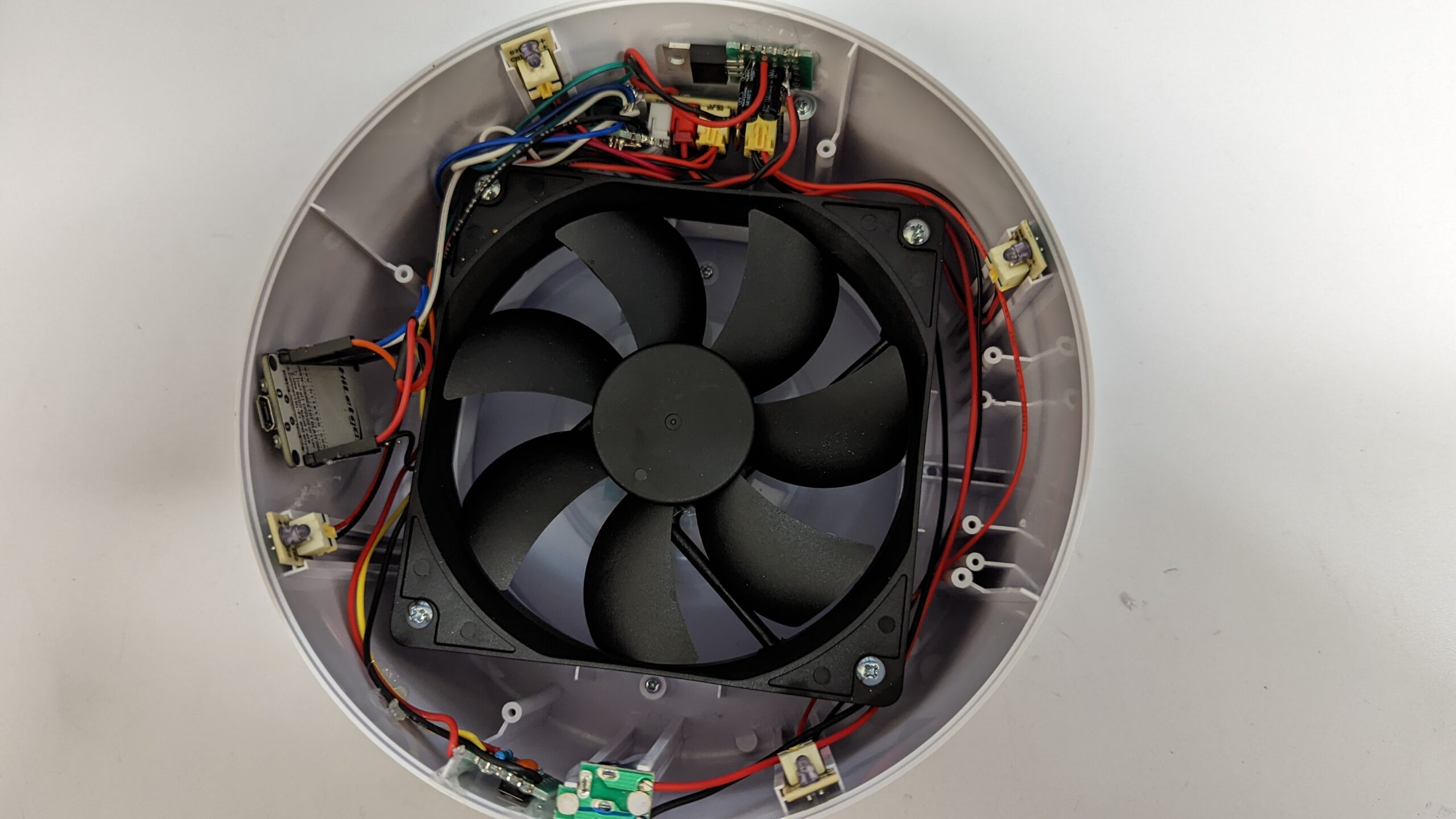
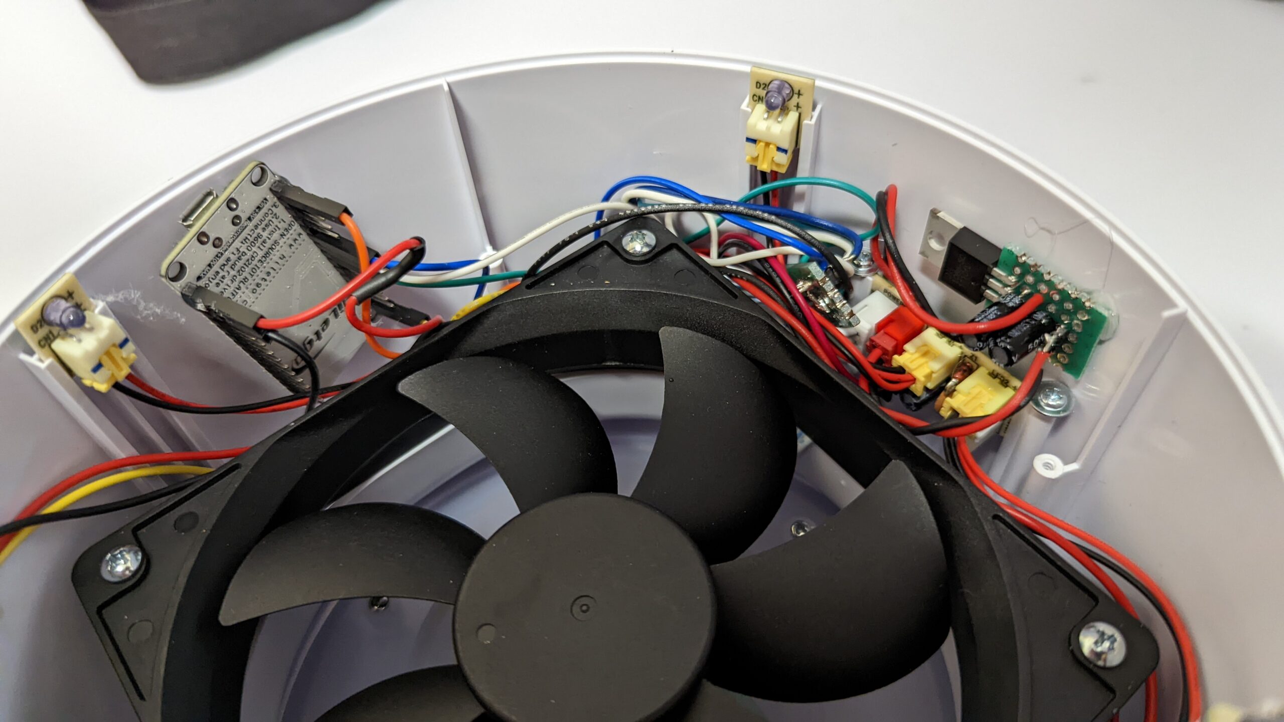
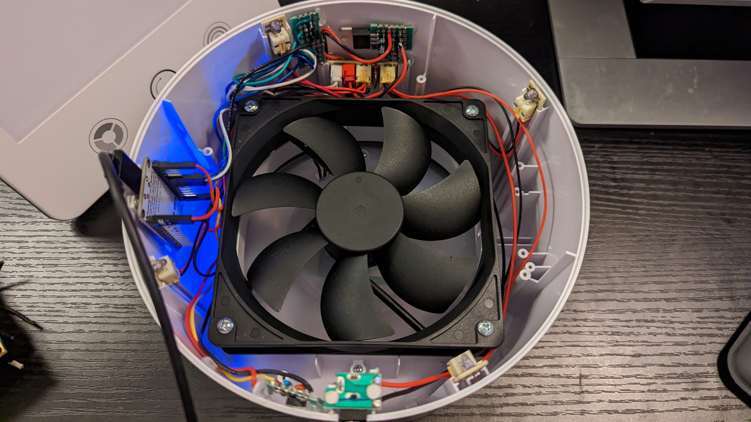
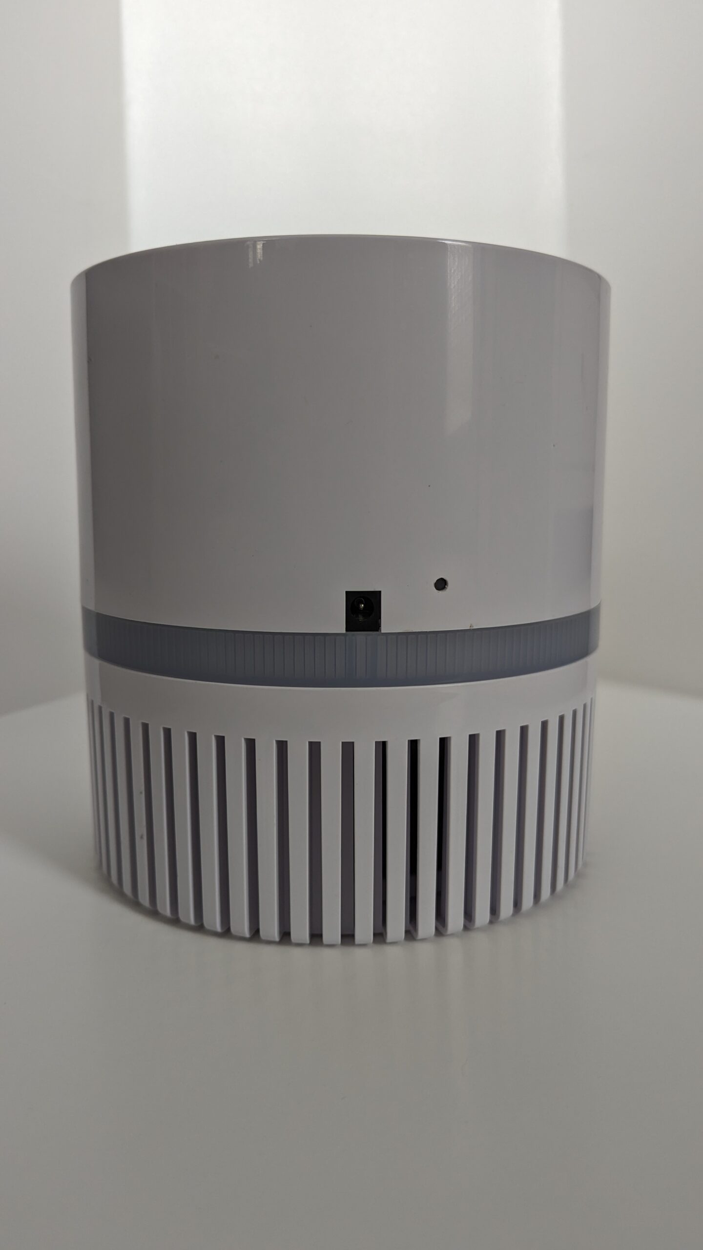
Putting the base back on and the device is as good as new, besides a new reset button hole.

Firmware V0
Both firmware versions live in the ESP8266_Air_Purifier repo on GitHub. This V0 firmware is in pretty rough shape and will not be updated.
First attempt at the firmware. The goal was to map out control of the hardware and get Alexa control working using fauxmoESP.
Hardware Control
Hardware Mapping:
- Blue Wire = LO = 1.8V is on (HIGH) and 0.0V is off (LOW)
- Indicates state
- Pin
D7
- White Wire = HI = 2.3V is on (HIGH) and 0.0V is off (LOW)
- Indicates state
- Pin
D6
- Green Wire = BTN = 5V pulled up, 0V on click
- Controls state
- Pin
D5is connected to a MOSFET connected to button
- Reset Button
- Pin
D0
- Pin
- Internal LED for status
- Use
LED_BUILTINpin
- Use
Note, 1.8V and 2.3V are both under the ESP8266’s nominal 2.5V high threshold. It has read reliably for me, but a comparator or a transistor buffer would be the proper fix.
States:
- OFF = 0
- HI = 1
- LO = 2
- ERROR = 3
We set up the hardware per normal for Arduino.
Our control scheme is a lookup table with entries for current and target transitions and a method to press the button “N” times with pause in between. We can skip entries where current state equals target state since there are no transitions needed.
| Current State | Target State | Transition Count |
|---|---|---|
| OFF | HI | 1 |
| OFF | LO | 2 |
| HI | LO | 1 |
| HI | OFF | 2 |
| LO | OFF | 1 |
| LO | HI | 2 |
The pulse routine is really simple:
#define PULSE_TIME                              (100L)

void transitionStatePulse() {
    Serial.println("Pulse");
    digitalWrite(CTRL_BTN_PIN, HIGH);
    delay(PULSE_TIME);
    digitalWrite(CTRL_BTN_PIN, LOW);
}
And in main we manage this with a queued pulses variable:
#define COOLDOWN_THRESHOLD                      (500L)

// Handle our queued pulses. This will block for one pulse at a time!
if (queuedPulses > 0 && (currentTime - cooldownTime) > COOLDOWN_THRESHOLD) {
    queuedPulses -= 1;
    cooldownTime = currentTime;
    transitionStatePulse();
}
Reading purifier state is simply converting from the two input signals (LEDs) into the state code.
#define readPurifierState() ((purifier_state_t)(digitalRead(LED_LO_STATE_PIN) << 1 | digitalRead(LED_HI_STATE_PIN) << 0))

// ... and in main loop
currentState = readPurifierState();
I also wrote a simple serial command set to jog the various functionality. I won’t repeat it here but it’s available in the source code.
Lastly, some of the housekeeping code with reset button monitoring and status LED output.
// Blink the LED at a certain rate dependent on state of purifier
//  Useful for debugging
if ((currentTime - blinkTime) > blinkDurationByState(hwState)) {
    blinkTime = currentTime;
    digitalWrite(LED_BUILTIN, blinkState);
    blinkState = !blinkState;
}

// Handle Reset button
bool btnState = readResetBtnState();
if (!btnState && prevBtnState) {
    resetTime = currentTime;
} else if (btnState && !prevBtnState) {
    if ((currentTime - resetTime) >= RESET_BTN_TIME_THRESHOLD) {
        flag_reset = true;
    }
    // Otherwise button press was debounced.
}
prevBtnState = btnState;

// Reset State Machine
if (flag_reset) {
    flag_reset = false;
    Serial.println("Button Held");
    Serial.println("Erasing Config, restarting");
    wifiManager.resetSettings();
    ESP.restart();
}
Wi-Fi Setup
One of the great things about the ESP8266 is the built-in Wi-Fi radio and library support for it in Arduino. Below is a code snippet of what I did for reference. I used WiFiManager library, which greatly simplifies the process. It has its own built-in login page and everything.
#include <WiFiManager.h>

// In setup
wifiManager.autoConnect("AP-ESP8266-Air-Purifier");

// In reset hook
wifiManager.resetSettings();
FauxmoESP
Normally, in order to connect to Alexa (or Google Home) your device needs to go through a cloud layer.
I didn’t want to do that to prove the hardware hack. Luckily there is a dodgy workaround where the device pretends to be a Philips Hue bulb that can locally connect to an Alexa smart speaker (technically it emulates the Hue bridge on the LAN, which is what Alexa’s local discovery finds). A library that exposes this is fauxmoESP. Unfortunately, the only functionality I could get working is ON/OFF control.
Setup is pretty straightforward.
#include <fauxmoESP.h>

static fauxmoESP fauxmo;

fauxmo.addDevice("air purifier");
fauxmo.setPort(80);
fauxmo.enable(true);
fauxmo.onSetState(fauxmo_callback);
The callback hook (and the number of pulses lookup from the table):
void fauxmo_callback(uint8_t id, const char * name, bool state, uint8_t value) {
    if (state && currentState == PURIFIER_OFF) {
        queuedPulses += numberOfPulses(currentState, PURIFIER_HI);
    } else if (!state && currentState != PURIFIER_OFF) {
        queuedPulses += numberOfPulses(currentState, PURIFIER_OFF);
    }
}

int numberOfPulses(purifier_state_t currentState, purifier_state_t targetState) {
    for (int i=0; i<transitionCountLookupTableSize; i++) {
        if (transitionCountLookupTable[i].current == currentState && transitionCountLookupTable[i].target == targetState) {
            return transitionCountLookupTable[i].transitionCount;
        }
    }

    return 0; // If no match in table, default to zero
}
Once I flashed this firmware, configured my Wi-Fi settings on the ESP8266 and connected it to my Alexa, I was able to toggle on and off the purifier. But this doesn’t quite do what I wanted with High, Low, and Off settings. Plus Alexa is convinced it’s a light and Google Home does not know this device exists.
Onto Firmware V1.
Firmware V1
For the second attempt at the firmware, we will use the same hardware mapping and control but swap out the clunky fauxmo library for something I have been cooking up as a larger scale side project called Okos Polip.
Update: I cracked it open again in February 2023 for firmware V1 with Okos Polip.
First, what is Okos Polip?
- It’s a web service that handles device-to-cloud communication by and for hobbyists
- It’s a firmware library (for Arduino) that affords connection over a simple protocol
- The library has hooks for a standard (but configurable) workflow
- It’s an API that a web service can hook into for device control (for instance, via Amazon Alexa).
In short it’s awesome and makes sense (disclaimer, I may be biased).
I eventually gave Okos Polip a write-up of its own in Okos Polip ~ My Device-to-Cloud Service.
So now let’s set up the global state for Okos.
#include <WiFiUdp.h>
#include <NTPClient.h>
#include <ArduinoJson.h>
#include <polip-client.h>
#include <ESP8266HTTPClient.h>

#define NTP_URL                                 "pool.ntp.org"
#define FALLBACK_AP_NAME                        "AP-ESP8266-Air-Purifier"

const char* SERIAL_STR = "air-purifier-0-0000";
const char* KEY_STR = "revocable-key-0";    //NOTE: Should be configured
const char* HARDWARE_STR = POLIP_VERSION_STD_FORMAT(0,0,1);
const char* FIRMWARE_STR = POLIP_VERSION_STD_FORMAT(0,0,1);

static StaticJsonDocument<POLIP_MIN_RECOMMENDED_DOC_SIZE> _doc;
static WiFiUDP _ntpUDP;
static NTPClient _timeClient(_ntpUDP, NTP_URL, 0);
static polip_device_t _polipDevice;
static polip_workflow_t _polipWorkflow;

static char _transmissionBuffer[POLIP_MIN_ARBITRARY_MSG_BUFFER_SIZE];
Notice, we need to create a few things:
- JSON document and the transmission buffer are the scratch space the API reads and writes through
- NTP client is useful for generating timestamps
- Okos Polip device and workflow objects.
Setting up the NTP is optional but worth it to provide accurate timestamps for logging. We could alternatively have hooked up an RTC. But since this air filter is always powered the extra network calls don’t matter for the power budget.
Below are the notes on how this NTP client should be used.
// In setup
_timeClient.begin();

// In main loop
_timeClient.update();

// Whenever a timestamp is needed
_timeClient.getFormattedDate().c_str()
Next, we need to configure our Polip device and workflow.
POLIP_BLOCK_AWAIT_SERVER_OK(); // We simply block until link established

// This defines our object using the constants and buffer
// These options are device dependent (and are configured server /schema side)
_polipDevice.serialStr = SERIAL_STR;
_polipDevice.keyStr = (const uint8_t*)KEY_STR;
_polipDevice.keyStrLen = strlen(KEY_STR);
_polipDevice.hardwareStr = HARDWARE_STR;
_polipDevice.firmwareStr = FIRMWARE_STR;
_polipDevice.skipTagCheck = false;
_polipDevice.buffer = _transmissionBuffer;
_polipDevice.bufferLen = sizeof(_transmissionBuffer);

// A workflow handles polling and pushing state for us
_polipWorkflow.device = &_polipDevice;
_polipWorkflow.hooks.pushStateSetupCb = _pushStateSetup;
_polipWorkflow.hooks.pollStateRespCb = _pollStateResponse;
_polipWorkflow.hooks.workflowErrorCb = _errorHandler;

unsigned long currentTime = millis();
polip_workflow_initialize(&_polipWorkflow, currentTime);
Then in the main loop, we need to feed the workflow. This will handle state change from server to device.
polip_workflow_periodic_update(&_polipWorkflow, _doc,
    _timeClient.getFormattedDate().c_str(),
    currentTime // from millis()
);
And when the user presses the button, we can detect a state change and report back.
// State input is either HI LED or LO LED not both. But it could be neither = OFF
// pin reads are shifted to produce state
// If both pins are high then we are in a hardware fault state
_prevState = _currentState;
_currentState = readPurifierState();
if (_prevState != _currentState) {
    if (_transitionActive) { // Expected transition occurred
        _transitionActive = false;
    } else {
        POLIP_WORKFLOW_STATE_CHANGED(&_polipWorkflow); // Report Here
        _queuedPulses = 0; // Override any future changes
    }
}
So far we have glossed over the callbacks we registered during workflow setup. These are defined in the user application and are where the control magic happens.
For this device all we care about is Okos Polip Device State (there are others like metadata, sensors, RPCs). Below is the implementation.
static void _pushStateSetup(polip_device_t* dev, JsonDocument& doc) {
    JsonObject stateObj = doc.createNestedObject("state");

    switch (_targetState(_currentState, _queuedPulses)) {
        case PURIFIER_OFF:
            stateObj["power"] = "off";
            stateObj["mode"] = "hi";
            break;
        case PURIFIER_HI:
            stateObj["power"] = "on";
            stateObj["mode"] = "hi";
            break;
        case PURIFIER_LO:
            stateObj["power"] = "on";
            stateObj["mode"] = "lo";
            break;
        case PURIFIER_FAULT:
            stateObj["power"] = "on";
            stateObj["mode"] = "error";
            break;
    }
}

static void _pollStateResponse(polip_device_t* dev, JsonDocument& doc) {
    JsonObject stateObj = doc["state"];
    const char* power = stateObj["power"];
    const char* mode = stateObj["mode"];

    purifier_state_t serverState;
    if (strcmp(power,"off") == 0) {
        serverState = PURIFIER_OFF;
    } else if (strcmp(power,"on") == 0) {
        if (strcmp(mode,"hi") == 0) {
            serverState = PURIFIER_HI;
        } else if (strcmp(mode,"lo") == 0) {
            serverState = PURIFIER_LO;
        } else {
            serverState = PURIFIER_FAULT;
            Serial.println(F("INVALID MODE PROVIDED BY SERVER"));
        }
    } else {
        serverState = PURIFIER_FAULT;
        Serial.println(F("INVALID POWER PROVIDED BY SERVER"));
    }

    if ((serverState != PURIFIER_FAULT)
            && (_targetState(_currentState, _queuedPulses + (int)_transitionActive) != serverState)) {

        if (_targetState(_currentState, (int)_transitionActive) == serverState) {
            _queuedPulses = 0;
        } else {
            _queuedPulses = _numberOfPulses(_currentState, serverState) - (int)_transitionActive;
        }
    }
}
A push happens when we indicate to the workflow that something has changed. The workflow uses the hook to convert user state into the JSON packet at the right time in the communication cycle with the server. (You may notice we still report a mode when the power is off. State persists at the top level in Okos Polip, and a reboot or power cycle should not clobber it.)
A poll happens when the workflow soft-timer triggers a request (and response) from the Okos Polip server with the latest state. Our callback hook must convert from the JSON state into our underlying hardware or control variables. It is up to us to handle any abstractions or discrepancies between current state and the requested server side state. Alternatively, we can always trigger a push to send the current state back to the server if it’s not repairable.
Lastly, Okos Polip should have an error handling hook (for logging at least).
static void _errorHandler(polip_device_t* dev, JsonDocument& doc, polip_workflow_source_t source, polip_ret_code_t error) {
    Serial.print(F("Error Handler ~ polip server error during OP="));
    Serial.print((int)source);
    Serial.print(F(" with CODE="));
    Serial.println((int)error);
}
Stitching this code with the existing hardware control yielded better control from the Okos Polip server.
However, that is where I dropped off on this project. I can log into the backend database and directly toggle the state with the air filter dutifully updating on its next poll. Or the database receives the user button press updates on next push. But I don’t have what I am calling the State API up to interface with Alexa or Google Home (nor any software to manage / design the device schema within Okos).
Per usual my project is about 50% done.
Final Thoughts
Overall this was a pretty straightforward and fun hacking project. It was nice to stretch my Arduino/ESP legs after work. There is plenty of work left, even with the hardware hack and the cloud connection done.
Okos Polip has a long way to go before it’s a fully functional system. Additionally, I need to build a software layer on top of Okos Polip to allow Alexa or Google Home to control them. Stay tuned.
The next device to get this treatment was the plant grow light, which reuses the button-pressing approach with a proper interface board and adds RPCs for its timer.